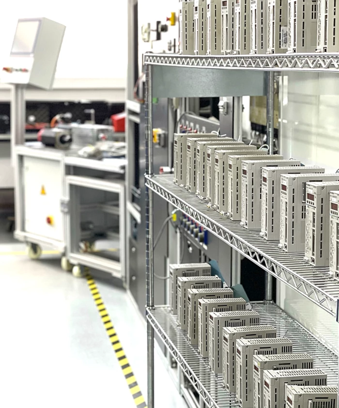
Drive Amplifier
For your information
- We offer for this displayed device sale, exchange and repair services.
- Prices for Servo-/Spindle Drives Power Supplies are standard prices for standard repair
- Devices for sell or exchange, was preventively overhauled in our workshop.
Learn more about...
Detailed information about Yaskawa SGDB Servopacks
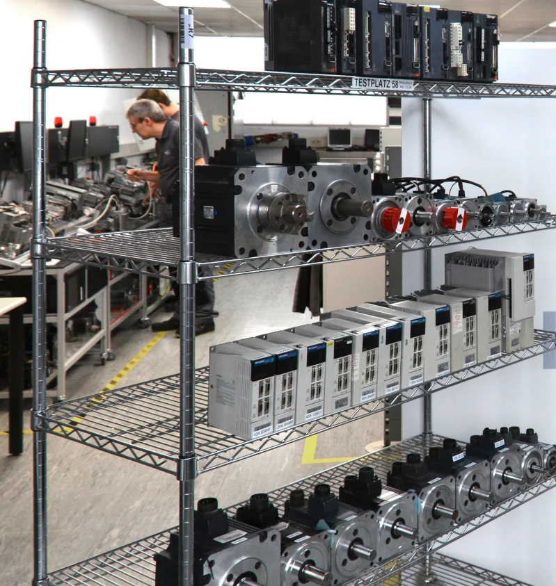
We offer serial repairs for this product series
- Repair of many electronic assemblies according to standardized repair procedures with documentation.
- A larger repair capacity is possible for the same or similar orders
- Target group: machine manufacturers, service companies and distributors
Access to years of experience, specialists and equipment.
Find out more about our series repairs
We Verify Your Drives and Electronic Components for Authenticity
Authenticity Check for Drives & Electronic Components: Confidence Before You Invest
Prevent failures caused by hidden counterfeits.
With our professional authenticity verification, you ensure
that your drives and system components truly meet original manufacturer quality before being installed in critical processes.
Why Authenticity Check Is Essential Today
The market for industrial drives, motors, and control components is globally interconnected. Components are traded through various channels, new, used, refurbished, or from warehouse stock.
As shown in our article Solutions Against Counterfeit Drive Components, products with unclear origin or altered substance repeatedly enter industrial supply chains.
For buyers, it is often not clearly recognizable:
- Whether it is an original product from the manufacturer
- Whether the device has been opened or technically modified
- Whether serial numbers and nameplates are authentic
- Whether all components correspond to the original condition
Especially in production-critical systems, unverified components can lead to downtime or consequential damage.
Professional authenticity verification provides clarity before the component is installed or resold.
What Exactly Is Checked During Authenticity Check?

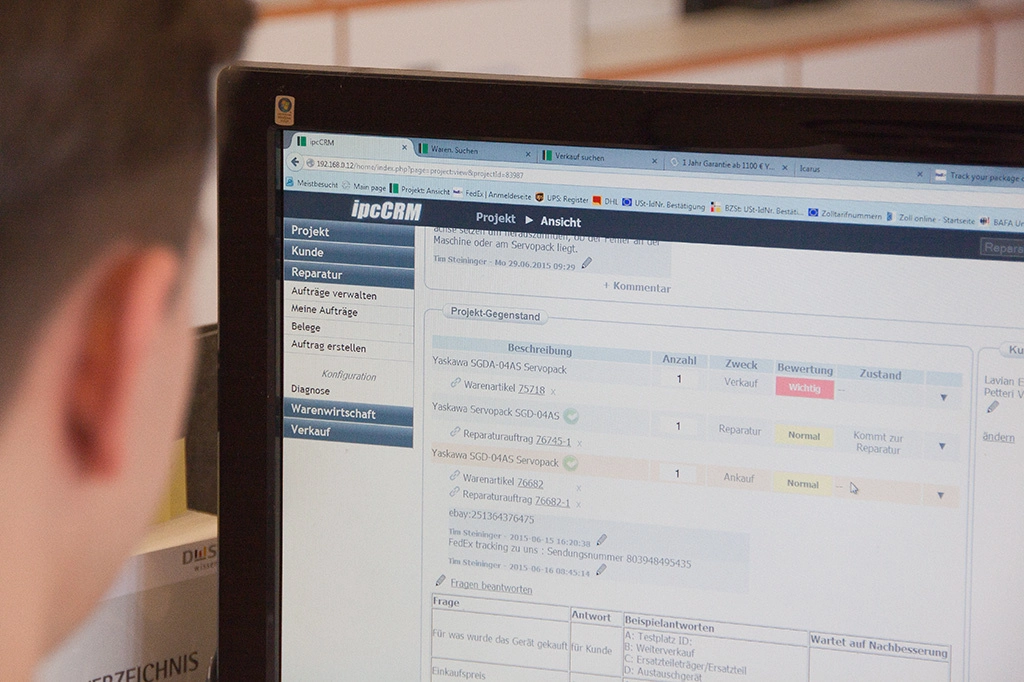
Inspection of Nameplate and Serial Number
We compare serial numbers, production markings, and device designations with our technical reference data and manufacturer standards, checking them for plausibility and irregularities.
Visual and Mechanical Inspection
Our technicians professionally open the device and examine housing, screws, seals, connectors, and internal assemblies for signs of manipulation, replacement traces, or deviations from the original condition.
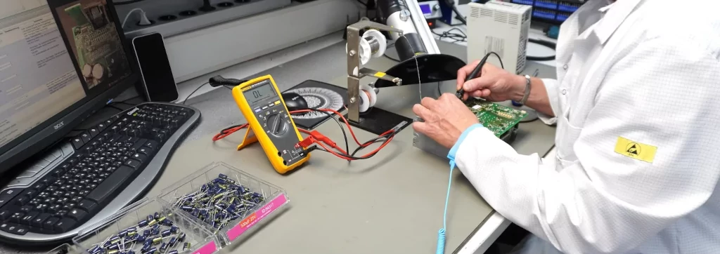
Electrical Measurements and Functional Testing
We test power and control units on our test benches under realistic conditions and verify whether the technical parameters comply with manufacturer specifications.
Software and Parameter Analysis
By reading firmware versions, parameters, and internal device data, we identify modifications, non-original configurations, or inconsistent software versions.
Comprehensive Technical Evaluation
Based on all inspections, we prepare a well-founded overall assessment, transparently document the device condition, and provide you with a clear recommendation for further use, repair, or replacement.
Who Our Authenticity Check Is the Right Choice For
Maintenance Personnel and Technicians
Safety before installation: verification of drives and motors to prevent unplanned downtime.
Purchasing and Procurement
Protection against incorrect purchases through technical inspection of serial numbers, condition, and authenticity.

Quality Management
Documented test results for internal quality assurance and audit purposes.
Machine and Plant Manufacturers
Reliable verification of components to safeguard customer projects and contractual commitments.
Distributors and Resellers
Transparent evaluation of device condition to enable trustworthy resale.
Learn More About Manipulation and Counterfeit Electronic Components in Our Blogs
Initial situation and fault description.
The Mitsubishi AC Servo Motor HG-KR43J was sent to us with a recurring and reproducible fault condition. During operation in combination with a MR-J4-40B Mitsubishi Servo Drive Unit, the following alarm occu...
A customer purchased what he thought were genuine XtraDrive XD-01-MSD0 drives from an Asian seller. The price was high, the trust was strong, and the units looked authentic.
However, the drives were never tested upon arrival. They remained in stora...
Why we are telling this story?
We regularly purchase servo drives as replacements for our industrial customers fast, reliable, documented. At the end of August 2025, a customer urgently needed a Yaskawa SGMSH‑30DCA6F‑OY. What initially looked l...
A customer brought us a Yaskawa SGMGS‑05A5W‑SE11 servo motor with a UTSAH‑B17BE encoder. His machine exhibited sporadic encoder faults. After each failure he had to realign the machine, and tools were damaged in the process. Because the motor ...