09.11.2025 by Viktor Siebert
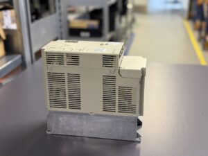
Repair of a Yaskawa SGDB-15VD AC Servopack with Alarm A10
The submitted Yaskawa SGDB-15VD produced Alarm A10 immediately whenever a motor rotation was commanded.
This alarm typically appears when the drive initializes successfully but does not receive stable feedback from the encoder or detects a phase mismatch between reference and feedback.
After the incoming inspection, the unit was opened for detailed examination. Slight oxidation was visible on CN2 pins, and the control PCB near the +5 V encoder supply showed discoloration. The board was thoroughly cleaned, and the connector pins were treated with contact cleaner. Insulation tests on the power section showed normal values.
Using a laboratory power supply, the logic voltages were verified (±12 V and +5 V stable). However, under simulated motor operation, the A10 alarm reappeared. Under the microscope, an intermittent trace beneath the differential receiver IC (SN75115) – responsible for the encoder’s A/B signals, was discovered.
The IC was desoldered, the tracks were inspected, and a new component was installed.
Following repair, the drive was tested on the bench using a Yaskawa SGMG-20A2AB AC servo Motor. The motor started immediately, current draw remained steady, and no alarm occurred. Several load cycles were performed over two hours without anomalies.
Subsequently, all power components were thermally checked, the output stage re-soldered, and electrolytic capacitors measured for ESR. The heatsink was cleaned, all mounting screws re-torqued, and new thermal pads applied.
A final full-load test using original performance curves confirmed proper operation and thermal stability.
Preventive Measures for the Customer
- Clean ventilation paths and heatsinks every 6 months.
- Inspect CN1 and CN2 connectors for oxidation or loosened pins.
- Measure supply voltage and phase balance annually.
- Route encoder cables separately from power lines.
- In dusty or oily environments, install an auxiliary fan or filter.
- Replace main electrolytic capacitors every 7–8 years to ensure long-term stability.
Conclusion
Alarm A10 in Yaskawa SGDB-series Servopacks commonly results from contact or feedback signal issues in the encoder path.
Regular cleaning, connector maintenance, and proper grounding prevent such malfunctions and guarantee reliable long-term operation in industrial environments.
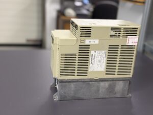
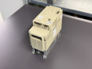
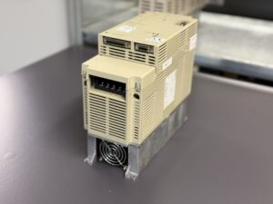
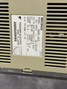
Information about the mentioned Servopack: Yaskawa SGDB-15VD Servopack
Mentioned Motor: Yaskawa SGMG-20A2AB AC servo Motor
Further details on our Yaskawa repairs can be found here: Yaskawa Sigma 1 Repair
📞 Feel free to contact us if you have any questions regarding your Yaskawa drive technology. Our team will be happy to assist you.
Device Specifications
| Specification | Value | Remark |
|---|
| Manufacturer | Yaskawa Electric Corporation | Japan |
| Model | SGDB-15VD | Servopack, Σ-I Series |
| Type | AC Servopack | Torque and speed control |
| Rated Power | 1.5 kW | For medium-size servo motors |
| Input Voltage | 3-phase 200–230 V AC | 50/60 Hz |
| Output Current | Approx. 10 A | per phase |
| Control Logic | 24 V DC | internal logic supply |
| Cooling | Convection cooling with heatsink | optional fan connection |
| Weight | Approx. 6 kg | Aluminum housing |
| Dimensions | 280 × 150 × 130 mm | (H × W × D) |
| Communication Interface | CN1 – Control, CN2 – Encoder | Compatible with USAFED and USAME motors |
| Manual Reference | Yaskawa AC Servo Drive M/F/S/D Series Bulletin TSE-S800-2.1J | |
Operating Environment & Compatible Devices
The SGDB-15VD belongs to Yaskawa’s first-generation Σ-I Servopack line and is widely used in machine tools, handling systems, and automated production lines.
It is typically paired with motors of the SGMG-20A2AB Sigma I series, each equipped with an incremental encoder (2500–6000 PPR).
The unit operates on a 200 V AC supply and connects to control and encoder lines via CN1 and CN2 connectors.
The recommended ambient temperature range is 0 °C to +40 °C, with relative humidity up to 80 % (non-condensing).
Functional Description
The SGDB-15VD is a fully digital AC Servopack designed for precise torque, speed, and position control of AC servo motors.
It uses a transistor-based PWM power stage to generate three-phase sinusoidal currents proportional to the reference input voltage.
Feedback from the incremental encoder (CN2 interface) closes the control loop, ensuring accurate and dynamic regulation.
The drive includes comprehensive protection features against over-current, over-voltage, over-temperature, phase loss, logic faults, and encoder communication errors.
A dynamic braking circuit is integrated and automatically activated in case of emergency stop or alarm.
The internal control electronics operate on ±12 V and +5 V rails that drive the IGBT gates, continuously monitored for consistency.
Alarm Codes & Troubleshooting
| Code | Description | Cause | Remedy |
|---|
| A01 | Over-voltage | Supply too high, insufficient regeneration | Check input power, verify braking resistor |
| A02 | Over-current | Short circuit in motor or faulty IGBT module | Inspect motor and output stage |
| A03 | Overheat | Ambient too hot or fan failure | Check cooling fan, clean heatsink |
| A04 | Under-voltage | Input below 180 V | Verify power supply |
| A05 | Control Error | 24 V logic voltage missing or unstable | Check power supply and fuses |
| A06 | Encoder Signal Error | Missing or wrong phase feedback | Inspect encoder cable and signal levels |
| A07 | Communication Fault | CN1 connection interrupted | Check control cable |
| A08 | Thermal Overload | Motor operated beyond rated load | Reduce load torque |
| A10 | Initialization Error during Motor Start | Unstable encoder feedback or phase mismatch | Inspect encoder connection, test motor feedback |
| A11 | CPU Error | Faulty logic board | Replace control PCB |
| A12 | Phase Loss | Open circuit on U/V/W phases | Check wiring and connectors |
Main Components
| Component | Designation / Code | Function | Service / Repair Note |
|---|
| Power Stage | Transistor Inverter (IGBT) | Converts DC to 3-phase AC | Inspect for thermal cracks |
| Control Board | CN1 Control PCB | Regulation & communication | Check optocouplers and op-amps |
| Encoder Interface | CN2 Connector Board | Processes motor feedback signals | Inspect solder joints and signal integrity |
| Rectifier Module | Diode Bridge | Converts AC to DC | Test for shorted diodes |
| Heatsink | Aluminum profile | Heat dissipation | Keep clean, add fan if needed |
| Current Sensors | Shunts / Hall ICs | Current feedback | Compare readings, verify offset |
| Capacitors | Electrolytics (400 V) | DC link smoothing | Measure ESR, replace if aged |
| Dynamic Brake | Relay + Resistor | Emergency stop protection | Test relay contacts |
| Display Module | 7-Segment LED | Alarm indication | Check segment output |