23.11.2025 by Viktor Siebert
Repair of a Mitsubishi MR-J3-10B Servo Drive with Error 32 Overcurrent
Initial Situation and Error Description.
The Mitsubishi MR-J3-10B was sent in with error 32 Overcurrent. According to the customer, the drive occasionally shut down during fast axis movements and dynamic acceleration profiles. These conditions typically place the highest electrical stress on the servo amplifier. Because the customer uses a large number of identical J3 units within their machines, a repair was the preferred option. Replacing the J3 with the J4 series would require extensive parameter adjustments, compatibility checks and time consuming commissioning work.
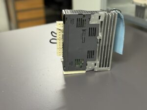
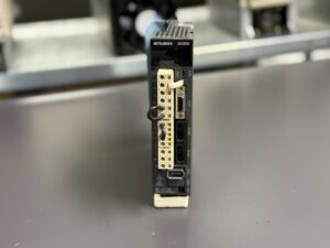
When the drive arrived at our facility, there were no signs of foreign repair attempts. All components, solder joints and mechanical elements were in original condition. The device instead showed the typical characteristics of long term industrial use. These included minor discoloration near the power elements, dust accumulation and progressive aging of the internal components.
Diagnostic Findings and Technical Assessment
During the visual inspection, we noted light thermal coloration near the power transistors which is normal after years of operation. The DC link capacitors showed the first signs of aging indicated by a slight reduction in effective capacity. The gate driver components also displayed thermal cycling stress but no visible damage.
Electrical diagnostics quickly identified the underlying reason for the overcurrent behavior. The internal current monitoring reacted more sensitively than normal when exposed to rapid load changes. According to the manual, error 32 may be triggered not only by a short circuit but also by drifting component parameters within the power stage. In this case, no hard failure was detected. Instead the power module and associated driver circuits showed age related drift which caused the protection function to activate earlier than intended.
Repair Process and Preventive Overhaul
Since no destructive failure was detected, we performed a complete preventive overhaul of the drive. The power module was removed, cleaned and electrically evaluated. During the preventive refurbishment we replaced:
- the DC link capacitors
- all gate driver components
- thermal interface materials
- insulation foils
- critical semiconductors within the gate driver path
- relays and power supply semiconductors
These measures ensure that the drive operates reliably again even during rapid acceleration sequences and high dynamic loads. The control board was cleaned and inspected under the microscope for micro cracks, oxidation or welding joint deterioration. No defects were found, but the age related condition justified a preventive refresh of several small signal components.
Test Procedure Under Real Operating Conditions
After the overhaul, the MR-J3-10B was tested on our servo test bench. We simulate dynamic load cycles, fast accelerations and thermal fluctuations similar to real CNC machine environments.
Measurements confirmed:
- stable gate drive signals
- symmetrical current distribution across the IGBT elements
- improved stability of the DC link
- no overcurrent triggers during the acceleration phases
- correct and predictable behavior of all protective functions
The drive passed the extended four hour load test without any irregularities. The internal temperature remained within the optimal range and the switching behavior was stable.
Customer Benefit and Sustainable Result
Through preventive refurbishment, the drive is restored to full operational condition without requiring modifications to machine parameters or control logic. This is particularly valuable for facilities operating many identical drives, as a series upgrade would require considerable time and integration effort.
The completed overhaul ensures long term operational reliability, minimizes unexpected downtime and provides a cost effective alternative to series replacement. The MR-J3-10B is ready for continued operation with significantly extended service life.

More Info & Contact
To mentioned Mitsubishi Drive: Mitsubishi MR-J3-10B Servo Drive Unit
More details about our Mitsubishi repair services can be found here:
Mitsubishi drive Repair by Industrypart
We regularly repair similar models, including:
MR-J3-10A
Technical Specifications
| Parameter | Value |
|---|
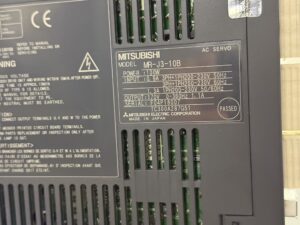
| Model | Mitsubishi MR-J3-10B |
| Type | AC Servo Drive |
| Power rating | 100 W |
| Input voltage | Single or three phase 200 to 230 V, 50 or 60 Hz |
| Input current | approx. 0.9 A |
| Output | 170 V, 0 to 360 Hz, 1.1 A |
| Protective functions | Overcurrent, overvoltage, encoder error, regenerative fault |
| Cooling | Convection cooling |
| Manufacturer | Mitsubishi Electric |
| Origin | Japan |
| Nameplate reference | Serial number TC300A287G51 |
| Manual reference | MR-J3 Series Alarm and Troubleshooting (Error 32) |
Operating Environment and Compatible Equipment
The MR-J3-10B is part of the third generation of the Mitsubishi MELSERVO family and is typically used in:
- CNC machine tools
- Industrial robots
- Gantry and handling axes
- Packaging machines
- Assembly and pick and place systems
Compatible motor families:
- HF-KP
- HF-MP
- HM-KP
- HG-KR
- HG-MR (depending on J3 or J4 compatibility)
The drive is backward compatible with many J2S and JN environments but requires parameter adjustments when replaced with MR-J4 units.
Functional Description
The MR-J3-10B provides high precision control for:
- Servo current
- Torque
- Speed
- Position
Communication modes:
- Pulse input
- Analog input
- SSCNET III (only for A type, not for this B type pulse unit)
Internal protection includes:
- IGBT current monitoring
- Encoder supervision
- DC link supervision
- Thermal protection
- Ground fault monitoring
The drive works with an internal power supply, control logic, gate drivers, power stage and feedback processing.
Alarm Messages and Troubleshooting
(Based on the PDF alarm table. Exact manual wording.)
| Code | Description | Cause | Solution |
|---|
| 10 | Undervoltage | Supply too low | Check supply wiring |
| 12 | Memory Error 1 | RAM failure | Replace drive |
| 13 | Clock Error | Control board error | Replace drive |
| 15 | Memory Error 2 | EEPROM failure | Replace drive |
| 16 | Encoder Error 1 | Feedback issue | Check encoder and cable |
| 17 | Board Error | PCB failure | Replace drive |
| 20 | Encoder Error 2 | Position feedback issue | Inspect encoder system |
| 24 | Main Circuit Error | Main circuit problem | Inspect wiring, replace drive |
| 25 | Absolute Position Error | Battery or encoder issue | Replace battery or encoder |
| 32 | Overcurrent | Short circuit on U V W, defective IGBT, ground fault or noise trigger | Check motor, wiring and drive |
| 33 | Overvoltage | DC link too high | Verify supply |
| 45 | Main Circuit Overheat | Drive overheated | Improve cooling |
| 47 | Cooling Fan Error | Fan failure | Replace fan |
Components
| Component | Code | Function |
|---|
| Control board | J3-C20 / BC386A742G52 C | Processing, control, parameter handling |
| Control board | J3-C20 / BC386A670G51 E F | I O processing and feedback |
| Power board | J3-P01F / BC386A495G56 A | IGBT stage, gate drivers, DC link |
| Power section | – | DC link, input filter, relay section |