03.11.2026 by Viktor Siebert
Mitsubishi MR-J2S-10B: Motor runs, DC bus voltage too low
The motor runs, but the drive still needs repair
During the incoming test of this Mitsubishi MR-J2S-10B, a connected motor could be commanded to rotate. However, the DC bus reading was only 222 V, which our workshop considered too low in the test setup used. A brief rotation test alone cannot establish that a servo amplifier is healthy. The customer’s description, measured values and functional checks must be considered together.
Fault reported from the machine
The customer reported that a low DC link voltage had been measured. A fault in the robot controller could no longer be acknowledged. After a replacement drive was installed, the machine worked again. This observation helped narrow down the problem. The customer’s description did not specify an exact robot-controller alarm number.
Incoming condition and alarm history
The unit appeared sound externally, with no evidence of a previous repair noted during inspection. The connected motor rotated, but the abnormal 222 V DC bus reading remained. The recorded alarm history included A.10, A.16, A.20 and A.25. Two A.25 entries were explicitly attributed to powering up during our own checks. The history is therefore not a list of simultaneous defects. In particular, an encoder replacement is not documented for this repair.
Distinguishing a measurement from a diagnosis
The technician recorded an expected bus voltage of approximately 300 V for the specific test setup. The measured 222 V is an incoming observation, not a universal limit for every operating condition. HCPL components were identified as suspect or defective in the cause assessment, and an overhaul was recommended. Stored alarms must be interpreted alongside the current condition, the connected motor and the test conditions.
Cleaning and component-level overhaul
Following approval, the servo amplifier was cleaned and overhauled. The repair entry specifies electrolytic capacitors and HCPL components, including components beneath the module. The work therefore extended beyond externally accessible areas. The documentation records the unit as cleaned, repaired and overhauled. Other work, such as replacing the entire power stage or updating firmware, is not documented for this case.
Final test with a motor
After the overhaul, the amplifier was tested again with a motor. The motor test, bus voltage and display were recorded as OK. Alarms were cleared and the rotary switch was returned to its previous setting. The original footage shows the test setup and diagnostic software; a 293 V bus voltage is visible near the end. That reading describes the moment shown, rather than guaranteeing the same value under every future load or supply condition. The repair was completed with the status repaired and tested on 22 October 2026.
What this repair demonstrates
A servo amplifier can rotate a motor while still exhibiting an abnormal electrical condition. Here, the customer’s report and the DC link measurement were important together. Retesting after the overhaul was equally important. The workshop footage documents the technical completion; it does not establish any particular duration of subsequent production operation.
Technical context
| Modell / Model | MR-J2S-10B |
|---|
| Leistung / Power | 100 W |
|---|
| Versorgung / Supply | 3~ 200–230 V AC / 1~ 230 V AC, 50/60 Hz |
|---|
| Schutzart / Protection | IP00 |
|---|
| Masse / Mass | 0,7 kg |
|---|
| Motorbeispiel / Motor example | HC-KFS13 |
|---|
Functions: current control, autotuning, vibration suppression. Verify the complete motor combination and settings before use.
Series alarm reference
A.10 undervoltage; A.12 memory 1; A.13 clock; A.16 encoder 1; A.17 board; A.20 encoder 2; A.24 main circuit; A.25 absolute position erased; A.32 overcurrent; A.33 overvoltage. General manual references, not ten confirmed faults in this repair. The B-series bus undervoltage threshold is 200 V DC or below. The incoming 222 V reading must not be equated with that threshold.
Prevention and repair preparation
Record alarm displays and operating conditions before removing the unit where possible. Preserve the nameplate details, motor assignment and existing settings. Have maintenance and electrical testing performed by qualified personnel. Clean installation conditions and unobstructed ventilation support operation. When sending a unit in, explain whether the problem occurs at startup, after warming up or during movement. This helps the workshop tailor its checks to the actual fault.
Price, availability and turnaround
Our product page provides current information and a way to request assistance for this model. A binding repair turnaround depends on the findings, required parts and requested service. Our Mitsubishi service page explains repair, exchange and sales options.
MR-J2S-10B: Produkt und Reparaturanfrage / Product and repair enquiry
Mitsubishi Service
Mitsubishi MR-J2S-B Instruction Manual SH(NA)030007-G, sections 1, 9, appendix 1
Repair photos and video
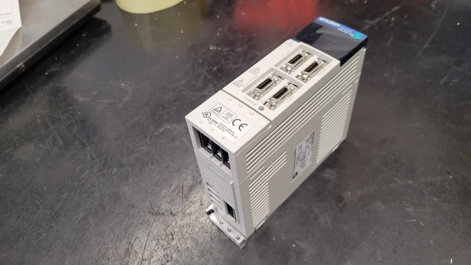 Mitsubishi MR-J2S-10B before repair
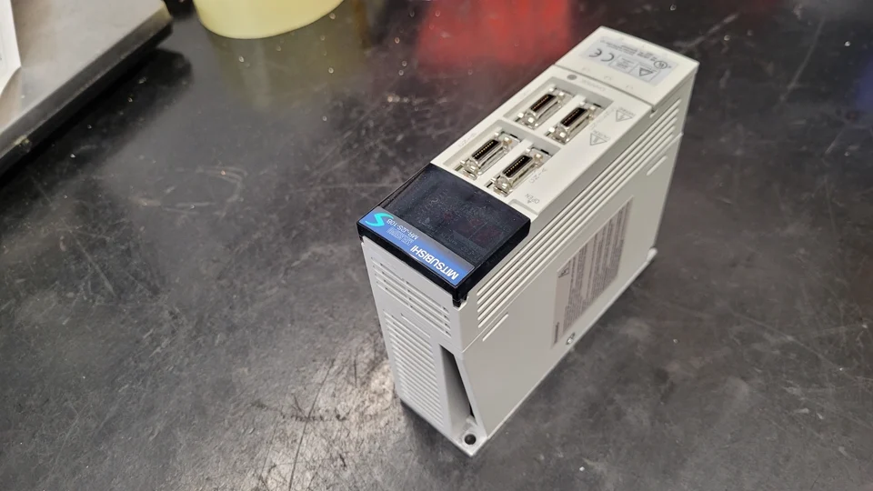 Mitsubishi MR-J2S-10B before repair
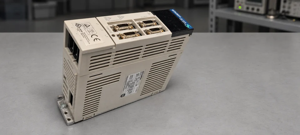 Mitsubishi MR-J2S-10B after overhaul
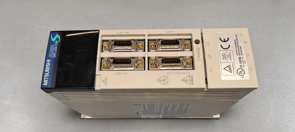 Mitsubishi MR-J2S-10B after overhaul