10.09.2025 by Viktor Siebert
Yaskawa XtraDrive XD-02-MSD0: A.10 and A.D0 – diagnosis, repair and testing
Several Yaskawa XtraDrive XD-02-MSD0 AC Servopacks arrived at industrypart with recurring A.10 alarms and, on some units, A.D0. This repair case illustrates why power electronics, cooling and position control must be considered together. An alarm narrows the investigation; it does not replace diagnosis of the drive and the connected machine.
Technical data and unambiguous identification
| Item | Value |
|---|
| Model | Yaskawa XtraDrive XD-02-MSD0 |
| Nameplate manufacturer | Yaskawa Europe Technology |
| AC input | 200–230 V AC; single-phase; 50/60 Hz; 3.4 A |
| Motor output | 0–230 V AC; three-phase; 2.1 A |
| Power rating | 0.20 kW / 0.27 hp |
| Pictured unit serial number | 02MSD0100860116 |
| Front marking | XD-02-MSD0 V3.30; separate marking V2.03 |
| Variant | XtraDrive-DP with PROFIBUS |
Electrical values were transcribed from the photographed nameplate. The 0.20 kW figure is a drive rating, not measured test power consumption. Input and output currents refer to different circuits. The front bears V3.30 and, in a separate location, V2.03; these markings should not be treated as the same firmware version without verification. The photographs identify one documented unit from the case, not the serial numbers of every unit received.
PROFIBUS variant, motors and replacement compatibility
The manufacturer selection guide identifies XD-02-MSD0 as a 200 W PROFIBUS variant. Listed combinations include suitable 200 W SGMAH and SGMPH motors. This does not approve every motor in those families: the complete motor model, encoder, voltage class and configuration must match. The front photograph shows the bus connector, address switches and BF/SF indicators.
“XD-02” alone is therefore insufficient for replacement selection. Before removal, record the complete order designation, visible version markings, motor assignment, parameter set and bus configuration. The controller must also address the replacement using the intended address and configuration. Matching dimensions and connectors do not establish functional compatibility.
How the power path and feedback work together
A servo amplifier combines motor power delivery with controlled motion. The power path provides motor current. Feedback reports actual motion, while the controller requests the desired motion. A temporary difference between commanded and actual position can occur; a growing or persistent difference is nevertheless an important diagnostic clue.
Similar-looking machine stops can therefore have different causes. An electrical motor-circuit fault calls for a different investigation from a stiff axis, disturbed feedback or unsuitable settings. The reported alarms in this case must be assessed separately even though they occur within the same drive family.
Functional areas and their diagnostic relevance
| Area | Purpose | Diagnostic focus |
|---|
| Power path and motor terminals | Deliver energy to the motor | Distinguish drive, cable and motor faults; an overcurrent alarm does not identify a single component. |
| Control electronics and parameters | Process motion commands | Compare the installed configuration with the saved machine setup. |
| Feedback interface | Measure actual motion | Consider encoder, cable, connectors and signal processing as one path. |
| PROFIBUS connection | Exchange data with the machine | Record address, configuration and status indications. |
| Cooling surfaces and air paths | Remove dissipated heat | Assess contamination and heat accumulation without assuming an electrical cause from these alone. |
This overview describes functional areas. Internal PCB order numbers were not documented for the pictured unit and have not been added.
Incoming faults, investigation and repair
The original workshop report described heavy dust deposits around the cooling area, impaired ventilation and unstable signal quality. The units were opened and cleaned of dust and oil residue. Repair included preventive overhaul and the documented replacement of selected age-sensitive components. The parts replaced in an individual unit belong in its repair record; this is not a universal replacement list for every XD-02-MSD0.
Functional and load testing followed, with particular attention to signal processing and feedback. The earlier report records the return of operational units. The original footage included here supplements that workshop account. A short video clip alone does not establish total test duration or specific measured values.
Narrowing down A.10 and A.D0
Timing matters: does the alarm occur at power-up, enable, acceleration or only after extended operation? This helps separate electrical faults, motion-dependent loading and thermal effects. Repeated resets without investigating the cause provide little additional evidence.
For A.10, investigate the complete power path. Motor cable and connectors matter alongside the motor and amplifier. Cooling problems are an additional finding, not an automatic explanation for every overcurrent event. A.D0 should not simply be described as “defective pulse control”: the relevant issue is the difference between requested and actual position. Comparing commands, feedback, mechanical loading and settings provides more clarity than premature component replacement.
General diagnostic guidance does not replace unit-specific repair testing. Work on the power section and electrical measurements require qualified personnel. Motor or cable insulation tests must not be applied through connected amplifier electronics without the appropriate procedure.
Selected XtraDrive alarms
A.10 and A.D0 are the reported faults in this case. Other entries provide context and are not additional findings.
| Code | Meaning |
|---|
| A.02 | Invalid EEPROM data |
| A.03 | Power-circuit sensing fault |
| A.04 | Parameter outside range |
| A.05 | Motor/drive mismatch |
| A.10 | Overcurrent / heatsink temperature¹ |
| A.30 | Regeneration circuit fault |
| A.32 | Regeneration overload |
| A.40 | DC-link voltage high |
| A.41 | DC-link voltage low |
| A.51 | Excessive speed |
| A.71 | High short-duration overload |
| A.72 | Sustained overload |
| A.73 | Dynamic-braking overload |
| A.7A | Heatsink overheated¹ |
| A.C1 | Uncontrolled motor motion |
| A.C9 | Encoder communication lost |
| A.d0 | Position error beyond limit |
¹ Temperature indications depend on power class. A.d0: Pn505 limit. Reference: XtraDrive 8U0108, Rev. C, chapter 9, pages 9-6, 9-21 and 9-26–9-28.
Prevention and preparing a repair enquiry
Clear air paths, clean cooling surfaces and a maintenance interval suited to the environment help limit thermal stress. Protect cables from abrasion, tension and contamination at connectors. A parameter backup together with photographs of drive and motor nameplates makes later work considerably easier.
For a targeted enquiry, provide the complete model, displayed alarm, when it occurs and a brief description of machine behaviour. Recent changes to the motor, wiring or parameters are also useful. This helps focus the investigation on the actual fault.
Sources and scope
Yaskawa Eshed Technology: XtraDrive User Manual, 8U0108, Revision C, November 2003; Omron XtraDrive datasheet I18E, XD- / XD-E.
Unit-specific electrical ratings: photographed nameplate. Case details: original industrypart workshop report and footage. General diagnostic guidance is distinct from documented work. Connection, configuration and recommissioning require documentation matching the actual variant.
Workshop and test-bench video
Drive photographs and nameplate
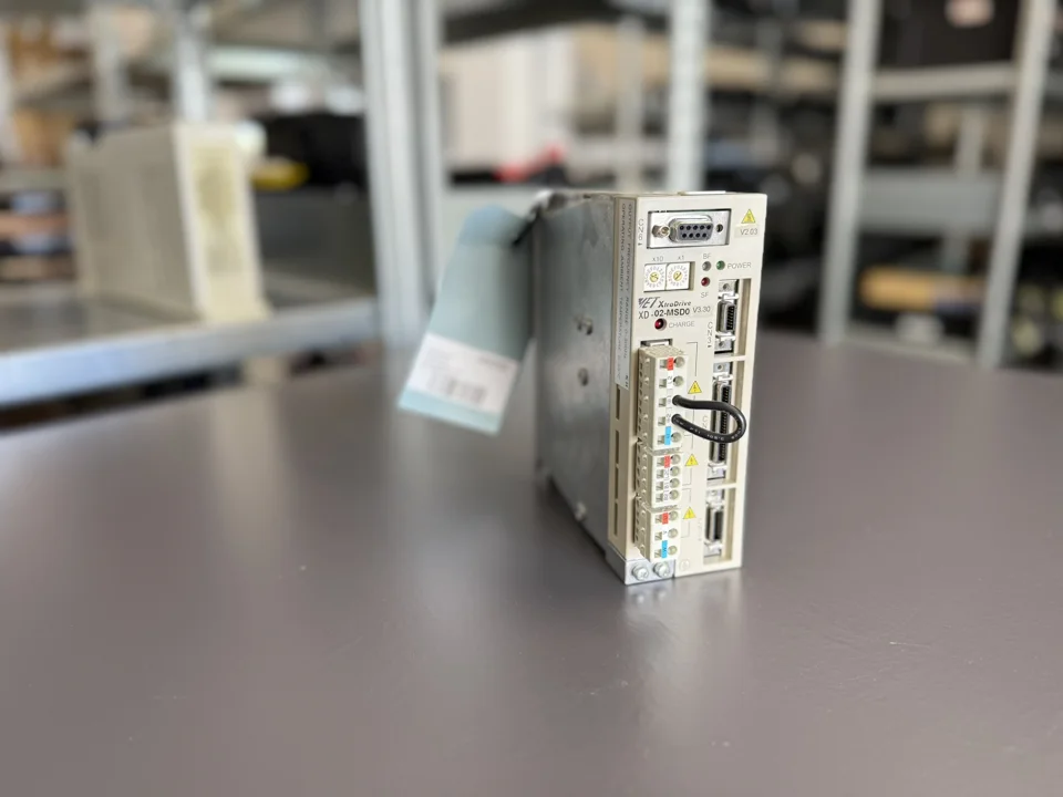 Unit from the repair case
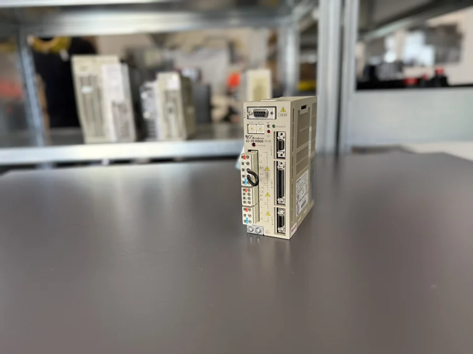 Front with interfaces and indicators
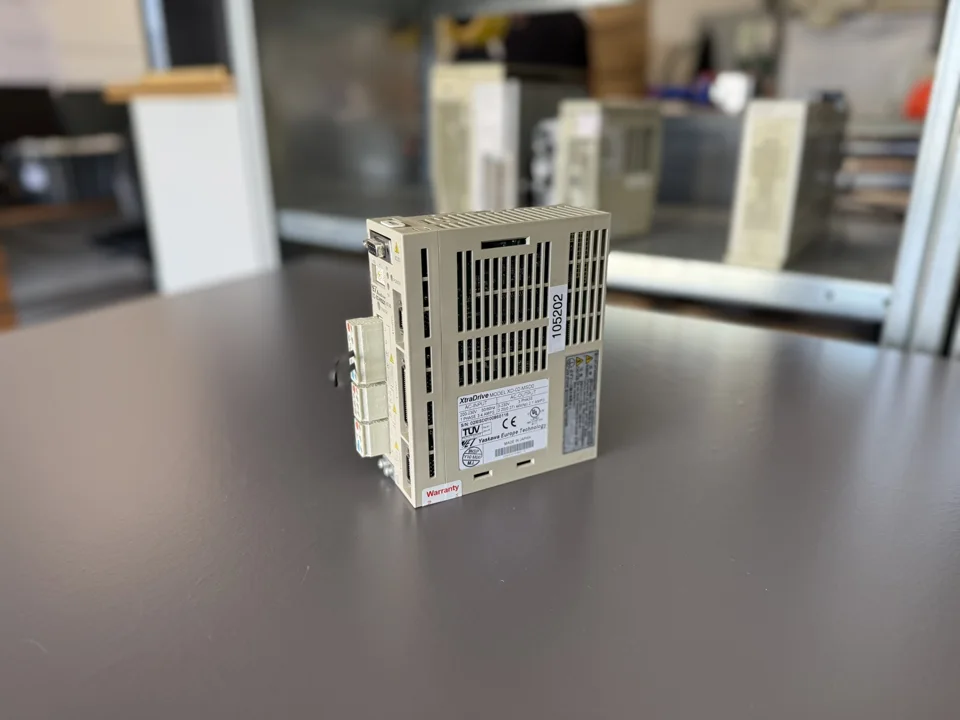 Side view
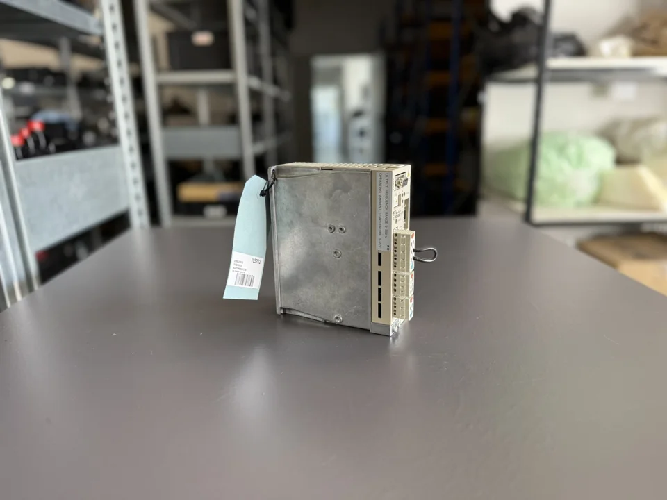 Additional unit view
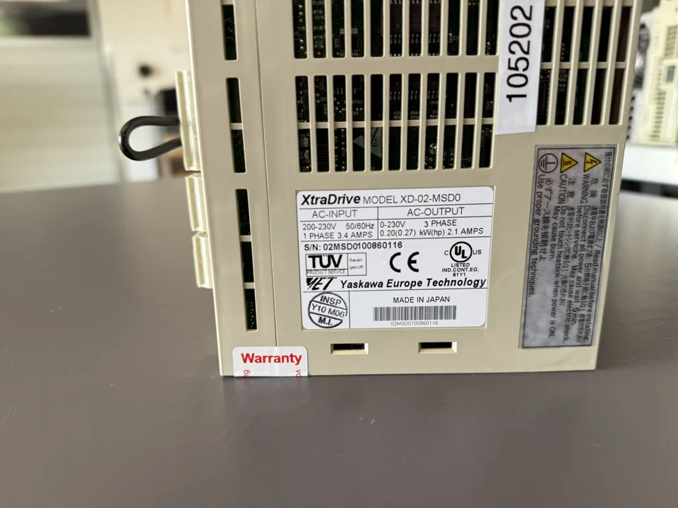 Nameplate with electrical ratings
Ask about repair and suitable units
Further details about the Yaskawa XD-02-MSD0 V3.30 in the shop and our Yaskawa repair service.