22.10.2026 by Viktor Siebert
Yaskawa UAASKD-08HHB11: noisy spindle motor and inaccurate positioning
A Yaskawa UAASKD-08HHB11 AC spindle motor arrived at industrypart with several symptoms: loud running noise, inaccurate positioning and vibration at low speed. Inspection identified damaged motor bearings, a defective encoder and a failed rear cooling fan. The repair therefore covered the mechanical bearing system, feedback and cooling. The motor was cleaned, repainted, adjusted and tested using a Yaskawa CIMR-M5A2022 drive.
Identification and technical data
| Item | Documented value |
|---|
| Manufacturer / model | Yaskawa UAASKD-08HHB11 |
| Device | AC Spindle Motor |
| Phases / poles | 3 / 4 |
| Power: 30-minute / continuous | 7.5 / 5.5 kW |
| Nameplate current | 47 / 37 A |
| Nameplate voltage | MAX. 230 V |
| Speed entry, literal | 500 / 8000 r/min |
| Insulation class | F |
| Standard / further plate markings | JIS C 4004; JP44; JCAOFA4S |
| Bearing references on the plate | 6310T2ZZAC3P5Q / 6210T2ZZAC3P5Q |
| Encoder according to repair record | Yaskawa UTMSI-10AABAAC |
| Drive used for testing | Yaskawa CIMR-M5A2022 |
The power figures refer to different duty ratings. A 7.5 kW rating for 30 minutes does not mean 7.5 kW continuous output; the plate specifies 5.5 kW for continuous operation. The two current figures must likewise be read in the context of those ratings. “MAX. 230 V” is a motor specification, not an instruction to connect the motor directly to the mains.
The speed entry is deliberately reproduced as “500 / 8000 r/min”. It is not used to infer a complete torque curve. Specifications for other UAASK variants, including base speed, mass or encoder resolution, are not transferred to the 08HHB11 suffix. The marking JP44 visible on the plate is also retained literally. The complete model designation and the particular machine configuration matter when selecting replacements and parameters.
Application, control and interaction with the drive
The spindle motor converts electrical power supplied by the drive into shaft rotation. The drive controls motor current, while feedback provides information about actual movement. Smooth running and repeatable positioning require the mechanical condition, feedback signal and control system to work together. Poor positioning cannot therefore be assigned to a specific component simply by listening to the motor.
The CIMR-M5A2022 is documented as the drive used on the test bench. This does not provide blanket approval to interchange arbitrary motors on that drive. Motor parameters, current limits, feedback, connector assignments and machine control requirements must be checked before combining components. An encoder that looks mechanically similar is not an equivalent replacement unless its electrical and mechanical specification also matches.
Components and their diagnostic relevance
| Component | Function | Finding in this case |
|---|
| Motor bearings and shaft | Rotor guidance and smooth mechanical running | Motor bearings damaged and replaced |
| UTMSI-10AABAAC encoder | Movement feedback for the drive | Defective; replaced and adjusted |
| Rear motor fan | Cooling airflow | Blocked by contamination; bearings also defective |
| Encoder compartment | Installation space for feedback components | Photograph shows substantial deposits |
| CIMR-M5A2022 | Motor control during testing | Used as test drive; no drive fault reported |
Reported symptoms and workshop findings
The motor was noisy and positioned poorly. Vibration also appeared at low speed. Workshop inspection identified damaged motor bearings. The encoder was defective as well and required replacement. The fan at the rear of the motor had stopped completely. Contamination was severe enough to prevent rotation, and the fan bearings were also damaged.
Visible deposits in the encoder compartment document the need for cleaning. The photograph alone does not establish their chemical composition or entry path. A specific coolant or oil leak is therefore not presented as a proven cause. No particular alarm code was supplied for this repair case.
Why noise, vibration and positioning errors require separate checks
Damaged rolling bearings can generate running noise and additional mechanical excitation. Defective feedback can instead corrupt or interrupt the information used by the control loop. Uneven movement and corrective control action can become particularly noticeable at low speed. Both the bearings and the encoder required repair in this case; the proportion of vibration attributable to either individual defect was not documented.
General fault isolation should also consider couplings, belts, spindle mechanics, motor wiring, connectors and shielding. Comparing different speeds and operating conditions can help separate mechanical noise from control-related oscillation. These checks are general technical guidance, not a claim that every listed procedure was performed during this repair. Control parameters should not be used to mask damaged bearings or defective feedback.
Cooling and the blocked fan
A stationary external fan reduces heat removal even if the motor itself continues to run. Independent ventilation is particularly relevant at low motor speed. Deposits can obstruct air passages and physically block the fan wheel. If fan bearings are also defective, cleaning alone will not resolve the complete fault. In this case, the existing fan was repaired by cleaning it and replacing its damaged bearings.
Test-drive alarm reference, not reported case alarms
The motor has no numerical alarm display of its own. The following selection belongs to the VS-626M5 drive system and provides context for possible messages at the test drive. It does not describe alarms reported during this job. Source: Yaskawa SIE-S626-7.5B, Table 12.2, pages 12-5 to 12-7.
| Code | Brief meaning |
|---|
| AL-01 | Overcurrent |
| AL-02 | Ground fault |
| AL-04 | DC fuse |
| AL-05 | Inverter overload |
| AL-06 | Motor overload |
| AL-07 | Locked-motor overload |
| AL-11 / AL-12 | DC bus: over/undervoltage |
| AL-13 | Low control voltage |
| AL-30 | Motor encoder disconnected |
| AL-31 / AL-32 | Overspeed / speed deviation |
| AL-33 | Motor output disconnected |
| AL-40 / AL-41 | Motor overheating |
| AL-42 | Motor thermistor disconnected |
| AL-48 | Inverter fan stopped |
| AL-60 | Orientation tuning incomplete |
| AL-61 / AL-62 / AL-63 | Reference signal / pulse count |
| AL-64 | Position encoder disconnected |
AL-48 concerns the fan inside the inverter, not the motor fan repaired here. Orientation alarms AL-60 through AL-64 depend on the installed orientation equipment. An alarm narrows down a fault category; it does not replace checking feedback, wiring, mechanics and configuration. The manual and configuration of the actual drive remain decisive.
Repair work and testing
The damaged motor bearings were renewed. The defective encoder was replaced; the recorded model is Yaskawa UTMSI-10AABAAC. The rear fan received new bearings and the deposits blocking it were removed. The affected parts were thoroughly cleaned, the motor was repainted and the required adjustments were completed. This addressed the identified mechanical, feedback and cooling faults together.
The motor was then tested on the Yaskawa CIMR-M5A2022. The supplied original recording documents the test run. Numerical positioning-accuracy results, a specific load cycle and an endurance test were not provided. Subsequent production operation at the customer is not claimed either. The documented scope is a repaired motor assembly tested on the stated drive.
Practical preventive maintenance
Regular maintenance should include fan operation, cooling passages and changes in running noise. A fan becoming louder or harder to turn deserves attention before cooling is lost. Deposits should be removed using an appropriate method without pushing contamination into bearings or feedback components. Cleaning and inspection must be performed by qualified personnel with the system safely isolated and de-energized.
If contamination returns, investigate its entry path on the machine. Cable entries, housing connections and the feedback area matter as much as the external appearance. Useful information for a repair inquiry includes a nameplate photograph, the speed and temperature at which symptoms occur, any alarm messages and whether the behaviour also appears with the machine mechanics disconnected.
Sources and scope
Case findings and repair work: supplied workshop information, original photographs and test video. Motor data: the UAASKD-08HHB11 nameplate. General alarm classification: Yaskawa VARISPEED-626M5/656MR5 User’s Manual, SIE-S626-7.5B, Chapter 12. Drive-system documentation does not replace a specific performance curve or connection approval for this motor variant.
Repair case video
Photographs before and after repair
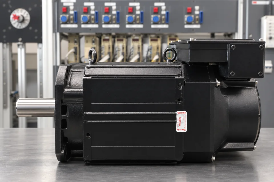 After repair: side view of the cleaned and repainted motor.
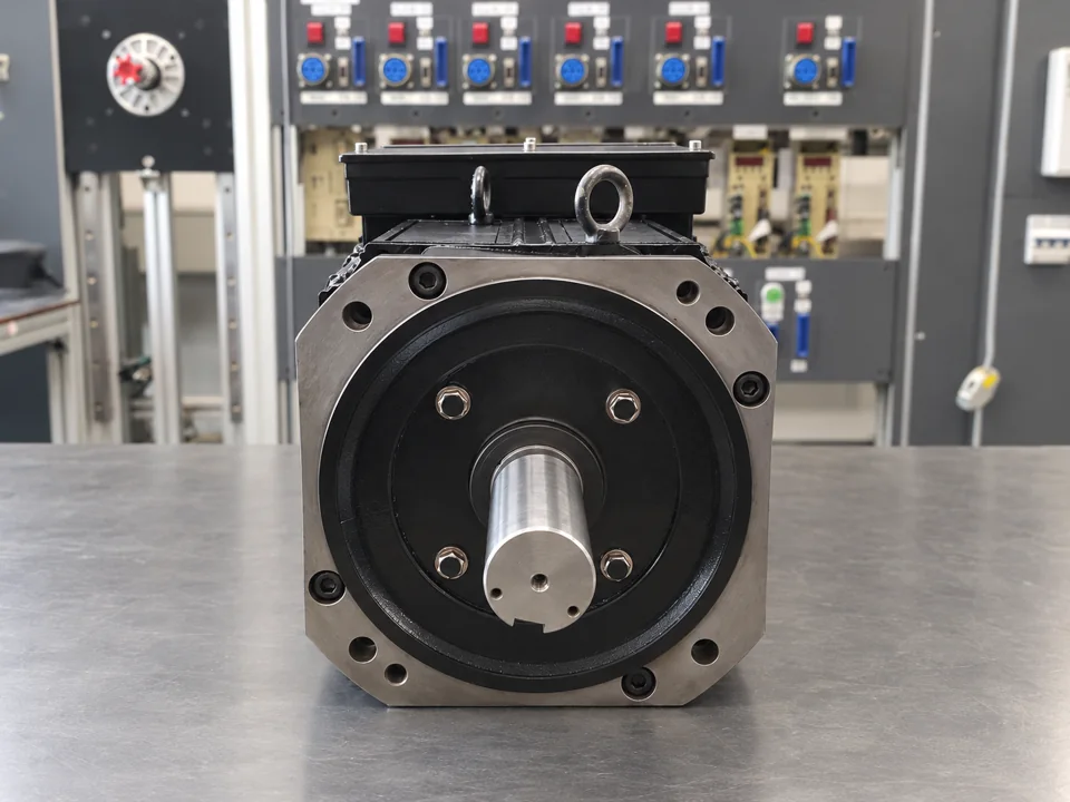 After repair: flange and shaft.
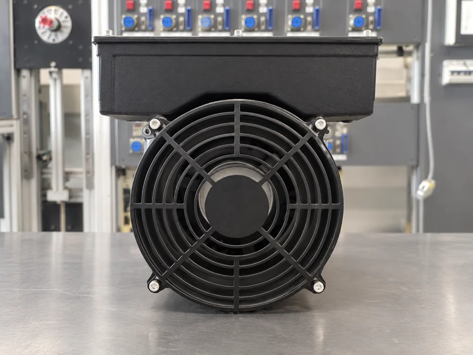 After repair: existing fan cleaned and fitted with new bearings.
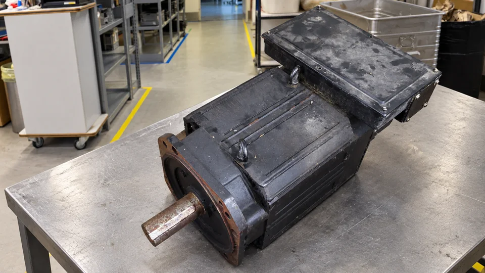 Before repair: condition on arrival.
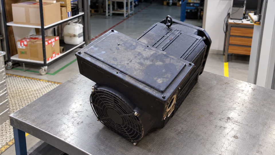 Before repair: fan side.
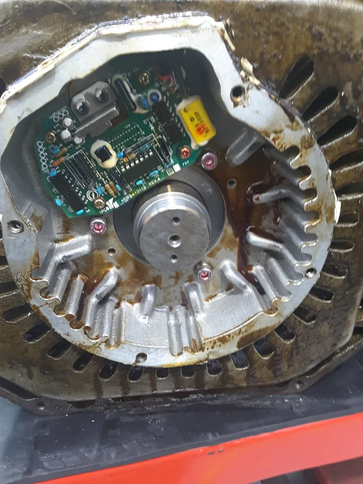 Before repair: deposits in the encoder compartment.
Request a repair
Yaskawa UAASKD-08HHB11 service · Yaskawa repair service