24.10.2026 by Viktor Siebert
Yaskawa SGMG-09V2ABC Servo Motor: Encoder Replacement and Overhaul
Yaskawa SGMG-09V2ABC: encoder replacement and complete overhaul
This Yaskawa AC servo motor arrived at industrypart with a suspected encoder fault. From approximately 1,000 rpm it produced pronounced noise, sounding as though it was continually trying to correct its motion. We replaced the encoder, overhauled the motor and subsequently carried out extensive testing and adjustment. The serviceable brake was cleaned and retained.
Motor identification and nameplate data
| Parameter | Value |
|---|
| Manufacturer / Hersteller | Yaskawa Electric |
| Model / Modell | SGMG-09V2ABC |
| Motor | AC Servo Motor |
| Rated output / Nennleistung | 0.85 kW |
| Rated torque / Nenndrehmoment | 5.39 N·m |
| Rated speed / Nenndrehzahl | 1,500 rpm |
| Rated voltage / Nennspannung | 200 V |
| Rated current / Nennstrom | 7.1 A |
| Duty / Betriebsart | CONT. |
| Insulation / Isolationsklasse | F |
| Serial / Seriennummer | 7P1460-4-13 |
| Date / Fertigungsangabe | 1998.03 |
| Original encoder / Bisheriger Encoder | Yaskawa UTOPH-81AWF |
| Replacement encoder / Neuer Encoder | Yaskawa UTOPH-81AiF |
| Brake / Bremse | SBR-112V-130B, DC 24 V |
The electrical ratings and serial number above come from the supplied motor nameplate. Encoder and brake designations are documented in the repair information. The nameplate speed is a rated operating point, not a statement of maximum permissible speed. The 200 V motor rating and the separate 24 V DC brake supply must not be confused.
Application, interfaces and replacement compatibility
The servo motor converts the amplifier’s controlled electrical output into shaft torque. Its feedback system supplies the motion information needed by the control loop. Power, feedback and brake functions must be matched to the actual machine wiring and amplifier configuration. This repair report does not establish a particular machine model or SERVOPACK pairing.
A similar housing or the same power rating alone is not sufficient for replacement selection. Check the complete suffix, mounting geometry, shaft, connector assignments, feedback interface, brake voltage and the approved motor data. The UTOPH-81AWF to UTOPH-81AiF replacement described here is a documented workshop action for this unit, not a blanket interchangeability statement for all applications.
Components and their diagnostic significance
| Component | Function and finding |
|---|
| SGMG-09V2ABC | Motor and shaft assembly; completely overhauled. |
| UTOPH-81AWF | Original feedback encoder, replaced during repair. |
| UTOPH-81AiF | New encoder installed; motor subsequently adjusted and tested. |
| SBR-112V-130B | 24 V DC brake; serviceable, cleaned and retained. |
| Bearings and seals | Replaced as part of the complete overhaul. |
| Housing and external surfaces | Cleaned and repainted. |
Why feedback faults can sound like a mechanical problem
The command specifies the requested movement. The encoder reports actual motion to the servo amplifier. The controller uses the difference to adjust motor current and torque. Unreliable feedback can therefore cause inappropriate corrections that are audible or felt as vibration. That mechanism explains why the reported sound was relevant to the encoder suspicion; the sound alone does not identify an encoder defect.
Mechanical noise may also arise from bearings, coupling alignment, driven machinery or a brake that does not release fully. Cable faults, poor contacts, shielding problems and unsuitable control settings can affect the same system. Recording the onset speed and comparing operation under defined conditions helps separate these possibilities. In this case, the confirmed work comprised encoder replacement and a complete mechanical overhaul; no individual signal measurements or load-test values were supplied.
Practical diagnostic guide and alarm assignment
No specific alarm code was reported for this case. Alarm numbers are assigned by the connected servo amplifier and its software, not by the motor model alone. The following table is a diagnostic guide, not a code list for an unidentified drive. For an exact alarm interpretation, record the amplifier model, complete display, operating state and alarm history.
| Observation / alarm group | Possible areas to investigate | Practical distinction |
|---|
| Noise from a specific speed | Feedback, bearing condition, resonance, coupling | Record speed threshold and whether it changes with temperature or load. |
| Encoder / feedback alarm | Encoder, cable, connectors, supply and interference | Compare signal and wiring requirements for the actual amplifier. |
| Position or speed deviation | Feedback, excessive load, mechanics, settings | Distinguish incorrect feedback from a motor unable to follow the command. |
| Overload / excessive current | Load, acceleration, brake release, winding or power circuit | A brake that remains applied can load the motor without being an encoder fault. |
| Heating or temperature warning | Duty cycle, ambient conditions, load and cooling surfaces | Relate temperature to actual duty; do not substitute peak ratings for continuous ratings. |
| Noise without an alarm | Mechanical wear or control oscillation below a trip threshold | Absence of an alarm does not replace a condition assessment. |
Repair, adjustment and testing
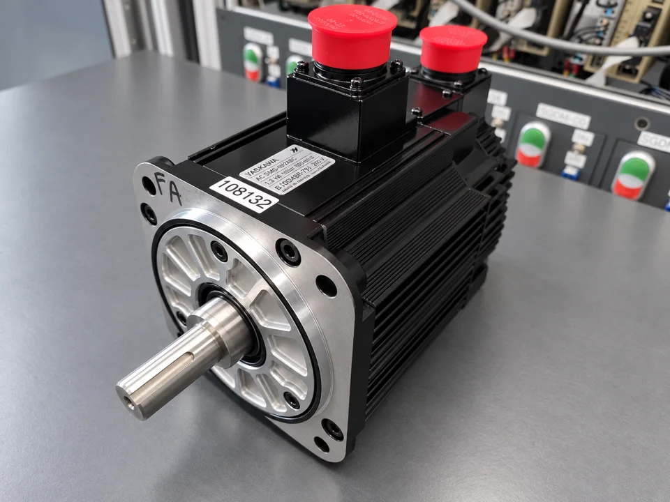
We replaced the UTOPH-81AWF encoder with a new UTOPH-81AiF. The complete overhaul included new ball bearings and seals, thorough cleaning and repainting. The SBR-112V-130B brake was found to be in order and was cleaned without replacement. After reassembly the motor underwent extensive testing and adjustment.
Feedback adjustment matters because mechanically fitting a replacement encoder is only part of the task. The motor and control system must also receive the correct motion relationship. The supplied test recording documents operation on the test setup. It does not establish a quantified load capacity or a specified endurance-test duration.
Preventive maintenance with practical benefit
Keep cooling surfaces and connector areas clean, protect seals from contamination and inspect cables for damage or strain. Compare operating noise over time under similar conditions. Record the speed at which a change begins, together with load, temperature and any amplifier alarm. Check the brake’s release function using the machine-specific procedure. These observations make a later diagnosis more focused than the description “motor is noisy”.
Technical reference
Yaskawa Sigma Series SGM*/SGDB User’s Manual, SIE-S800-26.4C, sections 4.4, 5.8, 5.9 and 12, provides general family-level information on feedback, brake interlocking, adjustment and maintenance. Its variant-specific ratings and SGDB alarm codes are not transferred to this undocumented drive pairing. Exact motor values above are taken from this unit’s nameplate.
Test video
 ▶ Testvideo auf YouTube ansehen / Watch test video on YouTube
Before and after repair
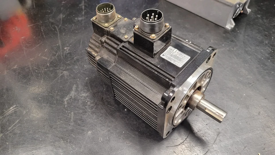 Yaskawa SGMG-09V2ABC: Before repair: shaft side
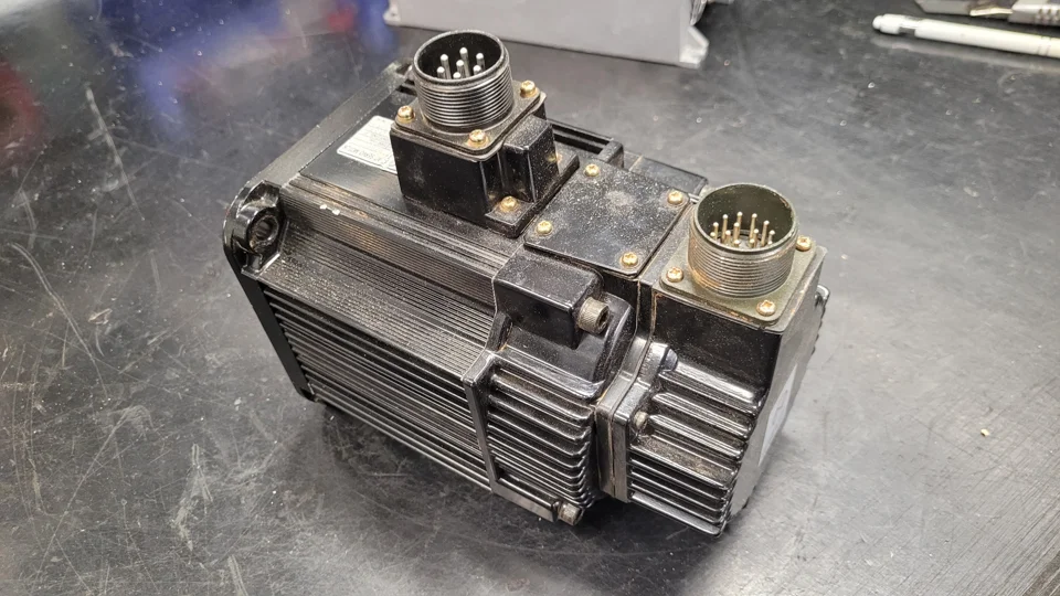 Yaskawa SGMG-09V2ABC: Before repair: rear view
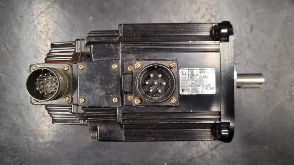 Yaskawa SGMG-09V2ABC: Before repair: connectors
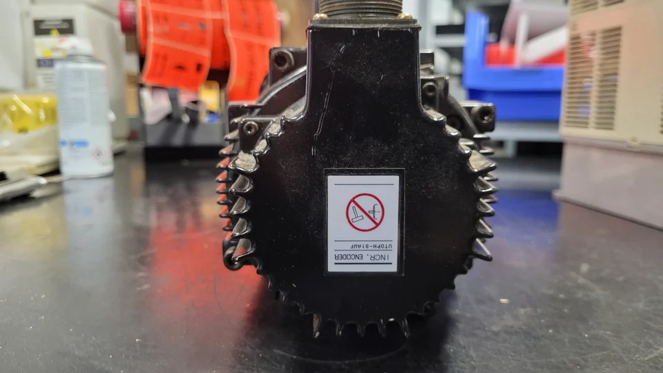 Yaskawa SGMG-09V2ABC: Original encoder UTOPH-81AWF
Yaskawa SGMG-09V2ABC: After repair: main view
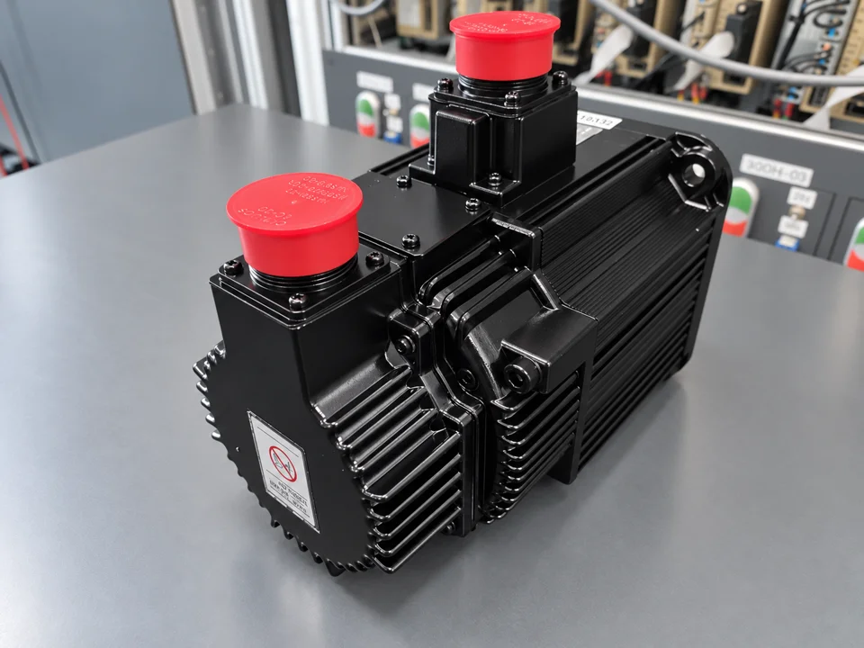 Yaskawa SGMG-09V2ABC: After repair: rear view
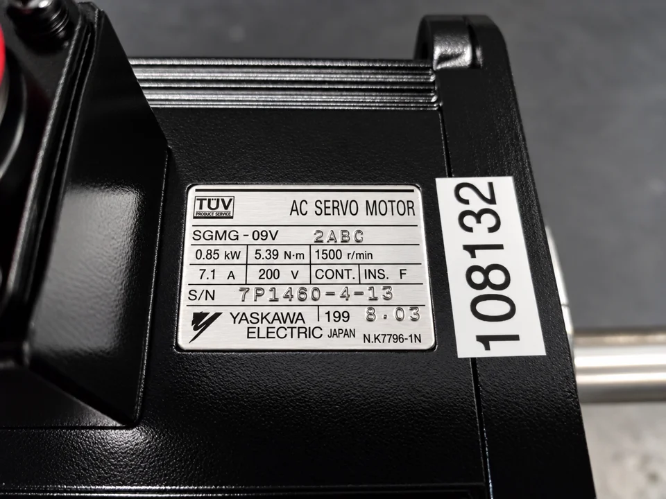 Yaskawa SGMG-09V2ABC: Motor nameplate
Request a repair assessment
Please send the complete motor designation, a nameplate photo, the amplifier model and a description of when the symptom occurs. Mention the speed threshold, load conditions and any alarm display. industrypart supports you with diagnosis, repair and preventive overhaul of industrial motors and drive electronics.
Yaskawa SGMG-09V2ABC AC Servo Motor
For more information about our Yaskawa motor and drive repairs, visit our Yaskawa repair service.