01.12.2025 by Viktor Siebert
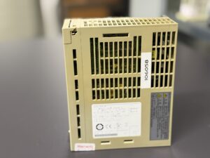
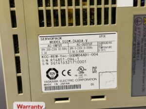
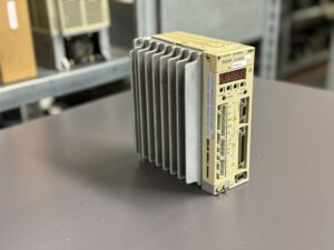
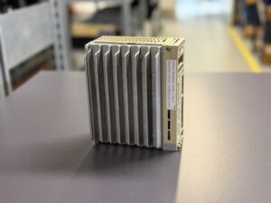
Repair of a Yaskawa SGDM-04ADA-V Servopack with Alarm A.10
Initial Situation.
The Yaskawa SGDM-04ADA-V was sent in with alarm A.10. According to the customer the alarm appeared when main power was applied together with the Servo ON signal. During our first test this behavior was reproduced instantly. When the main power was switched on and the servo was enabled, A.10 occurred immediately and visible smoke exited the drive. This strongly indicates a short circuit in the IGBT output stage.
Diagnostic Stage
After opening the device a thermal burn pattern around the transistor module was visible. PCB areas showed discoloration and several solder joints were heat damaged. Measuring the U V W paths revealed a direct short to ground. This corresponds exactly with the manual description for alarm A.10 where short circuits between U, V, W and ground or internal transistor failures are listed. Motor miswiring was excluded because the error appeared even without a motor connected.
Repair Process
The power section was fully disassembled. The defective transistors were removed and tested. Several semiconductor elements showed low resistance between collector and emitter. The complete drive was cleaned thoroughly.
The power stage including driver circuits, gate control and current feedback path was rebuilt. Damaged PCB traces were reconstructed. The temperature sensing path was tested because Yaskawa lists thermostat connection faults as possible A.10 triggers.
After rebuilding the unit was tested on our Sigma test bench using load profiles, thermal cycles, repeated Servo ON sequences, speed simulation, overload sequences and heat checks.
All tests were passed successfully.
Preventive Measures
Regular visual inspection of motor cables
Insulation testing of U V W against FG
Checking regeneration wiring
Ensuring sufficient cabinet cooling
Avoid frequent power cycling
Cleaning fans and heat sinks
Monitoring ambient temperature
Conclusion
Alarm A.10 in Yaskawa drives normally indicates a severe power stage problem. The smoke confirmed an IGBT short circuit. After full restoration and intensive testing the SGDM-04ADA-V operates reliably again. Proper maintenance helps to prevent future failures.
Further information such as price and delivery time for: Yaskawa SGDM-04ADA-V Servopack
More details about our Yaskawa repair expertise can be found here: Yaskawa SIGMA II repairs by Industrypart
📞 Please feel free to contact us if you have any questions regarding your Omron drive technology. Our experienced team is always available to assist you.
Device Specifications (Electrical & Physical)
| Parameter | Value |
|---|
| Input voltage | 1-ph 200–230 V AC, 50/60 Hz, 5.5 A |
| Output voltage | 3-ph 0–230 V AC, 0–300 Hz |
| Output power | 0.40 kW |
| Output current | 2.8 A |
| Series | Yaskawa Σ-II SGDM |
| Device type | AC Servopack |
| Cooling | Heat sink, passive |
| Ambient temperature | 0–55 °C |
| Protection class | IP1X |
| Encoder interface | Serial, Sigma II compatible |
| Manufacturer | Yaskawa Electric Corporation |
| Reference | Σ-II Manual table 11.1 / 11.3 |
Application Environment & Compatibility
| Parameter | Description |
|---|
| Application | CNC axis control, handling, automation |
| Compatible motors | SGM, SGMAH, SGMGH (Sigma II) |
| Motor power class | approx. 400 W |
| Interfaces | Pulse, analog, serial encoder |
| Typical machines | Small CNC systems, portal axes |
Functional Description
| Function | Description |
|---|
| Power conversion | 1-ph AC to 3-ph motor output |
| Current control | Via IGBT power stage |
| Speed control | Encoder-based feedback |
| Position control | Internal closed-loop control |
| Protection | Overcurrent, overheating, under/overvoltage, regeneration faults |
| Monitoring | DC bus, thermostat, IGBT, encoder communication |
Alarm Table (from Yaskawa Manual SGDM/SGDH)
| Code | Description | Cause | Solution |
|---|
| A.02 | Parameter breakdown | EEPROM failure | Initialize or replace |
| A.03 | Main circuit encoder error | Detection fault | Check supply, replace |
| A.05 | Combination error | Motor mismatch | Correct motor-drive combination |
| A.09 | Dividing ratio error | Invalid Pn212 | Adjust parameter |
| A.0A | Encoder model unmatched | Unsupported encoder | Use compatible model |
| A.10 | Overcurrent / Heat sink overheated | Short circuit U/V/W, ground fault, IGBT failure, thermostat fault | Check wiring, motor, replace drive |
| A.30 | Regeneration error | Fault in brake circuit | Check resistor |
| A.32 | Regeneration overload | Excess regeneration energy | Adjust load or resistor |
| A.33 | Main circuit wiring error | Wiring vs parameter mismatch | Correct wiring |
| A.40 | Overvoltage | DC bus too high | Verify supply |
| A.41 | Undervoltage | DC bus too low | Check voltage |
| A.51 | Overspeed | Feedback or phase sequence error | Check wiring |
| A.71 | Overload high load | Momentary overload | Inspect mechanics |
| A.72 | Overload continuous | Continuous overload | Check mechanical system |
Component List
| Component | Designation | Function |
|---|
| IGBT module | Power stage | Motor current generation |
| Control PCB | Main board | Signal processing |
| Rectifier | Diode block | AC→DC |
| Heat sink | Aluminum | Heat dissipation |
| Regeneration path | Brake transistor & resistor | Energy dissipation |
| Encoder interface | CN connectors | Feedback reading |
| Power supply section | Internal PSU | Internal DC rails |