21.03.2026 by Viktor Siebert
Repair of a Yaskawa SGDB-44ADG AC Servopack with alarm A.40 after enable
Initial situation and fault pattern.
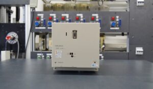
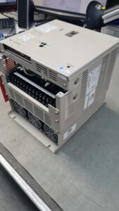
In this repair case, a Yaskawa AC Servopack SGDB-44ADG was received. The unit displayed alarm A.40 after the axis enable was activated. According to the customer’s description, the fault occurred directly when the unit was enabled. The drive did not go into fault only under load or after a longer running time, but already at a very early operating stage.
From a technical point of view, it is important to classify this fault correctly. In the available documentation environment, alarm A.40 is model related to a main circuit voltage error. This means a fault in the main circuit or DC link and not automatically a purely mechanical brake fault. In the same documentation family, faults of the regeneration path, overcurrent, overload and heat sink overtemperature are listed separately. This is decisive for the assessment, because a disturbed brake or regeneration function may be involved as a root cause, but the reported alarm itself technically points to the voltage conditions in the power section. The documentation of the SGDB Servopack family lists protection functions such as overvoltage, voltage drop, overload and heat sink overheat.
From the workshop perspective, it was therefore clear from the beginning that the alarm message alone was not enough. The complete cause and effect chain in the main current path, the regeneration branch and the power stage had to be examined.
Incoming inspection and first diagnosis
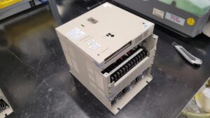
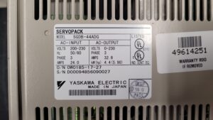
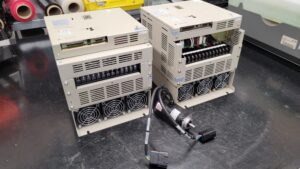
During the incoming inspection, the nameplate was recorded. The unit is a Yaskawa SERVOPACK SGDB-44ADG. The nameplate states AC input 200 to 230 V, 50/60 Hz, 3 phase, 24.0 A as well as AC output 0 to 230 V, 3 phase, 32.8 A and 4.4 kW (5.90 hp). These values match the 4.4 kW class of the SGDB or SR44BB device family. The related Yaskawa documentation assigns the 4.4 kW class to the SR44BB range and lists, among other data, max motor output 4.4 kW, continuous output current 33.0 Arms and a 200 to 230 VAC supply.
The first diagnosis focused on the following assemblies:
Power stage of the main current path
DC link with the associated voltage stressed components
Regeneration or brake stage
Control side monitoring of the main circuit
Contact points, solder joints and thermally stressed areas
Especially in older Servopacks of this design generation, faults often do not appear as one isolated total failure. They are much more often caused by thermally or age related unstable assemblies. Typical candidates are aged electrolytic capacitors, drifting resistors, pre damaged power semiconductors, aged snubber networks and solder joints with thermomechanical damage.
Technical analysis
The technical analysis showed that the fault was caused by ageing of the components. It was not only one defective part, but an overlapping fault pattern in the power stage and in the brake stage or regeneration stage.
The technical cause and effect chain was as follows:
Aged components in the power and brake branch caused unstable electrical conditions in the main circuit.
When the axis was enabled, the power stage was immediately energized or made ready for operation.
This created impermissible voltage conditions or implausible main circuit monitoring values.
The unit responded with alarm A.40.
It is important to separate alarm code and damage location. The alarm points to the main circuit. However, the visible or measured damage was not necessarily located exactly where the alarm text places its emphasis. In practice, this is typical. An aged brake or regeneration stage can indirectly influence the DC link in such a way that the monitoring of the main circuit responds. In the same way, a weakened power stage can cause the voltage stability to fall outside the permitted range during enable.
This is exactly why the statement that the brake function was faulty was technically understandable, even though the alarm code itself has to be interpreted more narrowly as a main circuit voltage error. From the workshop point of view, the alarm text alone was therefore not decisive, but the actual interaction of the affected assemblies.
Repair measures and refurbishment
After the technical fault isolation, the unit was professionally repaired. The power stage and the brake stage were completely refurbished.
The repair scope included technically reasonable and carried out steps such as:
Visual inspection of all thermally and electrically stressed assemblies
Incoming inspection for previous damage, discoloration and typical ageing patterns
Testing of the power semiconductors and their surrounding circuitry
Testing of the regeneration or brake branch
Replacement of aged or suspicious components
Rework of critical solder joints
Cleaning of assemblies and contact areas
Inspection of the connection areas in the main current path
Verification of the unit condition after refurbishment
Especially with older Yaskawa Servopacks, complete refurbishment of the affected power section is often more useful than replacing only one single failed component. The reason is that components with the same thermal and electrical stress usually age in a similar way. If only the obviously failed part is replaced, residual weakness often remains in the system. For a reliable repair, the entire functional block has to be considered.
Final function test
After repair, the Servopack was subjected to a final functional test. For this class of equipment, a proper function test typically includes:
Checking the supply and power on sequence
Checking the behavior during servo enable
Observing main circuit stability
Checking the alarm behavior
Thermal observation during test operation
Checking signals and basic regulator functions
The Yaskawa documentation refers to a proper supply of 200 to 230 V, an orderly start sequence and the checking of unusual vibration, noise and temperature rise during test operation. After refurbishment, the unit again showed stable behavior without a recurrence of the described fault pattern.
Result and conclusion
The repair was successfully completed. The fault after enable was caused by an age related defect in the area of the power stage and the brake stage. By completely refurbishing the affected functional groups, the unit was restored to a technically functional condition.
This case clearly shows that with older servo drives, the reported alarm code must not be viewed in isolation. Only the combination of alarm pattern, circuit understanding, assembly testing and bench testing leads to a reliable diagnosis. Especially with faults in the main circuit, the regeneration path or the brake branch, component ageing and thermal pre damage are very often the actual cause.
Further details on our Yaskawa repairs can be found here: Yaskawa Sigma 1 Repair
📞 Feel free to contact us if you have any questions regarding your Yaskawa drive technology. Our team will be happy to assist you.
Technical specifications
| Field | Value |
|---|
| Manufacturer | Yaskawa Electric |
| Device type | AC servo drive / AC Servopack |
| Model | SGDB-44ADG |
| Series | SGDB |
| Optional data | 200 V class, 3 phase, model related incremental encoder, power stage, brake or regeneration stage |
| Power | 4.4 kW according to nameplate |
| Input voltage | 200 to 230 V AC |
| Output voltage | 0 to 230 V AC |
| Rated current | Input 24.0 A, output 32.8 A according to nameplate |
| Control type | Transistorized PWM control, model related to the SR44BB device family |
| Feedback | Optical encoder / model related incremental feedback |
| Cooling | Heat sink cooled, natural or internal device cooling, no external fan evident for this class in the manual family |
| Protection class | not available |
| Mounting | Base mounted, model related |
| Ambient temperature | 0 to approx. 55 °C for Servopack according to manual family |
| Origin | Made in Japan according to nameplate |
| Product status | old / legacy product |
| Machine | not available |
| Industry | not available |
| Year of manufacture | not available |
| Country | not available |
Operating environment and application possibilities
The Yaskawa SGDB-44ADG belongs to an older AC Servopack generation for precise speed and motion control in industrial axis systems. Typical fields of application are machine tools, positioning systems, feeding units, handling units and general mechanical engineering applications with servo drives.
The manual family describes this device group for AC servomotors with optical encoder feedback, PWM power control and a 200 to 230 V supply. In practical operation, clean wiring, short signal lines, proper shielding and stable grounding are particularly important, because the devices can react sensitively to disturbances in the power and signal path.
Functional description
The Servopack handles the power supply and control of the connected servomotor.
The power stage converts the line supply into a controlled motor output voltage.
The control section processes command value, feedback and limit functions.
The feedback is model related via an optical encoder.
The protective functions monitor overcurrent, overvoltage, voltage drop, overload and heat sink overtemperature, among others.
The signal processing includes Servo ON, enables, monitoring and output signals via 1CN and the encoder connection via 2CN.
The supply is 200 to 230 V AC. In the manual it is described with a three phase main circuit and a single phase control circuit.
Cause and effect chain
Cause → Effect → Symptom
Component ageing in the power stage → unstable main circuit conditions during enable → alarm A.40 after Servo ON
Component ageing in the brake or regeneration stage → implausible voltage conditions in the DC link → main circuit fault instead of stable enable
Thermally aged solder joints or components → sporadically faulty power transfer → fault directly when activating enable
Possible additional fault source: reduced electrical reserve in the DC link → increased sensitivity to switch on and enable peaks → recurring voltage fault
Alarm messages and troubleshooting
| Alarm code | Description | Cause | Measure |
|---|
| A.10 | Overcurrent | Short circuit, defective power semiconductor, motor or wiring fault | Check power stage, motor cable and motor |
| A.20 | Blown fuse | Fuse in main circuit tripped | Check power stage and short circuit cause |
| A.30 | Regeneration error | Fault in regeneration branch | Check braking resistor, regeneration path and surrounding circuit |
| A.40 | Main circuit voltage error | Main circuit or DC link voltage out of range | Check main circuit, power stage and regeneration stage |
| A.51 | Feedback overspeed | Implausible feedback or control fault | Check encoder, signal cable and parameter setup |
| A.70 | Overload | Momentary overload | Check load, mechanics and current draw |
| A.71 | Overload | Overload condition in operation | Check utilization and axis mechanics |
| A.72 | Overload | Continuous overload | Eliminate thermal and mechanical cause |
| A.81 | Heat sink overheat | Heat sink over temperature | Check cooling, ambient temperature and load |
| A.8F | Power supply line open phase | Phase loss in the supply | Check mains supply and wiring |
Note: The A.xx designations are model related from the available SGDB alarm table. In addition, the Yaskawa documentation for the device family lists protection functions such as overcurrent, overvoltage, voltage drop, overload and heat sink overheat.
Assembly overview
| Assembly | Function | Notes |
|---|
| Power stage | Converts line energy into controlled motor power | thermally highly stressed, typical ageing area |
| Control board | Control logic, protective functions, signal processing | sensitive to overvoltage and ageing |
| Power supply / control section | Supplies the internal electronics | stable auxiliary voltages required |
| Brake or regeneration stage | Energy dissipation during braking, stabilization of the DC link | relevant in this repair case |
| DC link | Energy storage and voltage level of the main circuit | central to alarm A.40 |
| Heat sink | Heat dissipation of the power stage | watch for contamination and thermal ageing |
| Encoder feedback | Feedback for control and monitoring | check cable, plug and signal quality |
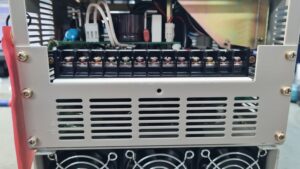
| Connectors | Power and signal contacts | check for contact faults and heating |
| Input terminals | Mains supply | check phases and screw connections |
| Output terminals | Motor connection | check insulation condition and tight connection |
Tests
| Test | Result / goal |
|---|
| Visual inspection | Previous damage, ageing and discoloration identified |
| Incoming inspection | Fault pattern after enable reproducible |
| Assembly testing | Power stage and brake stage isolated as fault area |
| Component testing | Age related weaknesses identified |
| Solder joint inspection | Critical thermal areas checked |
| Cleaning | Clean assembly basis established |
| Function test | Stable behavior after repair |
| Enable test run | No recurrence of the described fault pattern |
| Thermal observation | Unremarkable behavior after repair |
| Final inspection | Unit functional |
Repair measures
| Measure | Carried out |
|---|
| Visual inspection | Yes |
| Incoming inspection | Yes |
| Main circuit fault isolation | Yes |
| Power stage inspection | Yes |
| Brake stage inspection | Yes |
| Replacement of age related components | Yes |
| Rework of critical solder joints | Yes |
| Cleaning | Yes |
| Function test | Yes |
| Final enable test | Yes |
Preventive measures
Before work: Switch the system off with no voltage present, secure it against being switched on again, wait for the discharge time, and verify that no voltage is present. Measurements on live parts must only be carried out by qualified electricians.
With older Servopacks, operators should pay particular attention to thermal ageing. Regular visual inspections for discoloration, smell, dust contamination and warmed connection points are useful.
The ambient temperature of the Servopack should be kept low. The manual family recommends keeping the temperature around the unit low and keeping the cooling area clean.
Signal and encoder lines should be short, shielded and routed separately from power cables. The documentation names shielded cables and short cable lengths as important measures.
In the case of sporadic faults or faults that appear directly after enable, the main circuit, regeneration path, connectors, solder joints and aged capacitors should be checked at an early stage.
Regular cleaning and visual inspection help to avoid consequential damage and unplanned downtime.
Function test bench
| Test sequence | Result |
|---|
| Apply supply voltage | Unit starts up in an orderly way |
| Activate enable | no renewed alarm A.40 in the described condition |
| Observe main circuit behavior | stable |
| Basic controller function | available |
| Short thermal test | unremarkable |
| Final inspection | passed |
Result
The Yaskawa SGDB-44ADG was restored to a functional condition after refurbishment of the power stage and brake stage. The cause was age related weakness inside the power electronic assemblies. The reported alarm A.40 had to be understood as a main circuit fault, while the actual cause lay in the interaction between the main current path and the brake or regeneration stage.