25.10.2025 by Viktor Siebert
Repair of a Yaskawa SGDB-10VD Servopack
Repair Description
The received Yaskawa SGDB-10VD displayed the error A.C2 – Encoder Phase Detection Fault. The customer reported that the fault appeared intermittently, sometimes after five minutes, sometimes after one hour of operation. The motor was sent together with the drive to identify the root cause.
Initial testing showed that the motor encoder was providing faulty feedback signals. However, even after replacing the motor with our reference unit, the same error occurred, indicating a secondary fault inside the servopack itself. Oscilloscope measurements on the encoder feedback circuit revealed unstable signals generated by the control board. The encoder supply voltage intermittently dropped, causing feedback loss and resulting in the A.C2 alarm.
Further analysis showed that the encoder supply section on the control board had been damaged by voltage spikes, likely originating from the power supply section. These voltage surges affected both the encoder driver on the control board and the motor’s encoder. Such dual faults are rare but critical because incomplete repair would lead to repeated failures.
After a complete overhaul of the control board, including cleaning, inspection of all circuit paths, and replacement of critical signal components, the servopack was tested on our Yaskawa test bench under load conditions. The long-term test with a reference motor showed stable operation with no further interruptions or alarms.
At the same time, the customer’s motor, type SGMG-09V2ABC, was completely overhauled. The installed encoder UTOPH-81AWF was replaced with a new re-engineered version from our stock. After adjustment and isolation testing, the motor and drive were tested together. The system operated flawlessly and with full stability.
This case demonstrates that encoder-related faults should always be diagnosed across the entire signal chain, from the drive to the motor. Simply replacing the encoder would have left the internal defect within the drive unnoticed, leading to future failures. Thanks to detailed diagnostics and preventive measures, both units were restored to full functionality, ensuring long-term reliability for the customer.
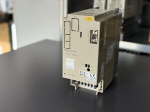
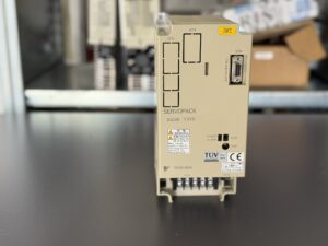
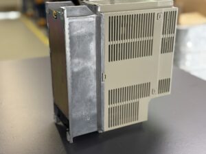
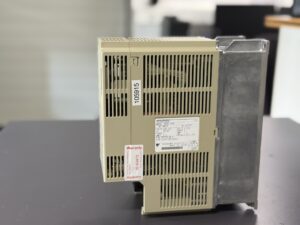
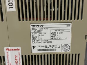
Information about the mentioned Servopack: Yaskawa SGDB-10VD Servopack
Mentioned Motor: Yaskawa SGMG-09V2ABC AC Servo Motor
Encoder: Yaskawa UTOPH-81AWF Re-Engineering-Newpart UTOPH-81AiF
Further details on our Yaskawa repairs can be found here: Yaskawa Sigma 1 Repair
📞 Feel free to contact us if you have any questions regarding your Yaskawa drive technology. Our team will be happy to assist you.
Device Specifications
Overview
The Yaskawa SGDB-10VD is an AC servopack from the Sigma I series, designed for precise motion and position control. It operates with a 200–230 V three-phase power supply and is used in demanding industrial environments such as CNC machines, pick-and-place systems, or automation equipment. The unit features a solid construction with a control board containing a dedicated encoder interface, compatible with various motor types.
Model Designation
Model: SGDB-10VD
Series: Yaskawa Sigma I
Rated Power: 0.85 kW (1.14 hp)
Input: 200–230 V, 3 phase, 8.0 A, 50/60 Hz
Output: 0–230 V, 3 phase, 7.1 A
Manufacturer: Yaskawa Electric Corporation, Japan
Protection Class: IP1X
Year of Manufacture: 2000
Technical Data
| Parameter | Value |
|---|
| Input Voltage | 200–230 V AC, 3 phase |
| Rated Output Power | 0.85 kW |
| Output Current | 7.1 A |
| Input Current | 8.0 A |
| Frequency | 50/60 Hz |
| Control Method | PWM inverter, sinusoidal drive |
| Feedback Type | Incremental or absolute encoder (UTOPH / UTOPI / UTOPH-AWF) |
| Cooling | Forced air, top-mounted fan unit |
| Ambient Temperature | 0 – 40 °C (operation) |
| Humidity | Max. 90% (non-condensing) |
| Weight | Approx. 3.2 kg |
Connections
- R/S/T: Three-phase AC input 200–230 V
- U/V/W: Output to the servo motor
- CN1: Control and command signals (Enable, Speed, Alarm Reset)
- CN2: Encoder feedback
- CN3: Communication or option interface
- FG: Protective earth
Control Board and Assemblies
The SGDB-10VD has a modular structure consisting of:
- Power stage (IGBT module)
- DC link circuit with rectifier and charge/discharge resistors
- Control board BN634A818G51 with encoder driver and signal processing
- Driver ICs for encoder signal amplification and power supply
- Temperature sensors and fan control circuit
Typical weak points include aged capacitors, worn fans, damaged encoder supply circuits, and thermally stressed solder joints in the signal section.
Alarms and Fault Messages (Sigma I Series)
| Code | Description | Cause | Corrective Action |
|---|
| A.00 | Absolute Encoder Data Error | Faulty or missing data from the absolute encoder | Check encoder and cable |
| A.04 | User Constant Setting Error | Parameter inconsistency or corruption | Reload parameters |
| A.10 | Overcurrent | Short circuit, defective power section | Inspect motor cable, test power stage |
| A.20 | Blown Fuse | Input fuse blown | Replace fuse, investigate cause |
| A.30 | Regeneration Error | Regenerated energy cannot be dissipated | Check braking resistor |
| A.40 | Overvoltage | Excessive DC bus voltage | Check supply voltage |
| A.51 | Feedback Overspeed | Encoder feedback exceeds maximum speed | Verify parameters |
| A.70–A.72 | Overload | Mechanical overload, blocked brake | Check load, monitor temperature |
| A.81 | Heat Sink Overheat | Heat sink temperature too high | Check fan and airflow |
| A.C2 | Encoder Phase Detection Fault | Missing or distorted encoder signals | Check encoder, cable, and control board |
| A.C4 | PC Disconnection | Communication loss between drive and controller | Check CN1/CN2 connection |
| A.F1 | Power Supply Line Open Phase | Supply phase interruption | Inspect power input |
| A.PF | Digital Operator Transmission Error | Communication error with operator panel | Check connection |
Typical Applications
The SGDB-10VD is used in older CNC systems, assembly machines, conveyor systems, and handling modules. It is commonly paired with Yaskawa SGMG, SGMAH, and SGMPH motors and served as the foundation for the later Sigma II (SGDH) generation.
Service Notes
A preventive overhaul is recommended every 10–15 years. This should include:
- Replacement of all electrolytic capacitors in power and control sections
- Replacement of the fan unit
- Cleaning and inspection of CN1/CN2 connectors
- Isolation test of the power module
- Verification of encoder supply voltage stability
Regular cleaning of ventilation paths and inspection of cooling fins significantly extend the lifetime of the unit.