03.10.2026 by Viktor Siebert
Yaskawa SGDB-10ADG: Express repair with A.C2 and A.C3 alarms
A Yaskawa SGDB-10ADG Servopack from Austria arrived for express repair with A.C2 and A.C3 recorded in its alarm history. Alongside repairing the unit, the customer had a key requirement: preserving the existing drive parameters. We completely overhauled the servo amplifier. Backing up the settings is a standard part of our approach to the SGDB series.
The repair case at a glance
Unit: Yaskawa SGDB-10ADG servo amplifier
Customer region: Austria
Alarm history: A.C2 and A.C3
Service: Express repair with a complete overhaul
Key customer requirement: Preserving the existing parameters
A.C2 and A.C3: indications of encoder feedback faults
The alarm reference used for this repair case identifies A.C2 as “Encoder output phase alarm” and A.C3 as “Encoder phase A and B disconnection”. Both concern encoder feedback: the encoder supplies the drive with information about motor movement.
Stored alarms provide useful diagnostic clues, but do not by themselves establish a currently reproducible fault or identify a defective component. Potential areas for investigation include the encoder, its cable and connectors, as well as internal signal processing and its power supply. For this unit, our workshop assessment also considered the internal power supply and power output stage. This assessment must be distinguished from the general meaning of the alarm codes.
Parameter backup: preserving the machine settings
A servo amplifier’s parameters adapt it to its application. Depending on the version, they affect functions such as control behaviour, limits and interfaces. Repairing or replacing a drive therefore involves more than matching its model designation.
For the SGDB series, we routinely read out and back up the existing parameters. If restoration becomes necessary, we can refer to this saved configuration. This preserves an important basis for subsequent commissioning. When replacing a unit, its version, motor, encoder and interfaces must also match the machine.
Complete overhaul and test station documentation
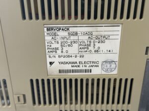
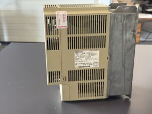
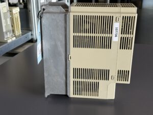
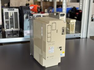
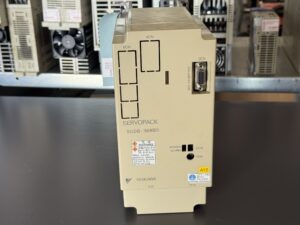
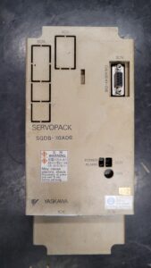
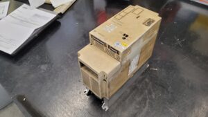
We completely overhauled the received SGDB-10ADG as part of the express repair. The photographs document its condition before the work and show the unit in a cleaned condition afterwards. The accompanying video shows the connected Servopack at the test station.
When recommissioning the customer’s machine, checking the existing encoder cables and connectors remains important. If an alarm recurs, its exact wording and operating conditions help narrow down the fault: does it appear at power-up, at servo enable or only during movement?
Repair video and photographs
Technical specifications
| Item | Specification |
| Manufacturer | Yaskawa Electric |
| Model | SGDB-10ADG |
| Alternative spelling | SGDB10ADG |
| Unit type and series | Servopack / servo amplifier, SGDB Sigma I |
| Input | 200–230 V AC, 3 phases, 50/60 Hz, 8.0 A |
| Output | 0–230 V AC, 3 phases, 7.0 A |
| Nameplate power rating | 0.85 kW / 1.14 HP |
| Origin | Made in Japan |
| Cooling | Heat sink and ventilation openings visible on the unit |
| Customer region and service | Austria, express repair with complete overhaul |
| Alarm history | A.C2 and A.C3 according to the case description |
| Documentation | Nameplate photograph; component list; Alarm Display Contents, Table 5.3, pages 5-25 and 5-26 |
Application environment and compatible equipment
Servopacks of this series are used in controlled machine axes. The customer’s particular machine and associated motor model are not identified for this case. Before replacement, check the complete unit version, motor, encoder, interfaces and parameters. The abbreviated designation SGDB alone is insufficient proof of compatibility.
Functional description
The power section converts the incoming electrical energy into a controlled three-phase motor output. The controller processes commands and feedback. The encoder provides information about motor movement; faults in its signals can prevent controlled operation. The internal power supply provides the electronics with operating voltages. Monitoring functions report unacceptable conditions, whose actual cause must then be investigated.
Components
The designations and quantities come from the supplied component list. The functional descriptions and inspection suggestions are general technical explanations, not a list of replaced parts.
| Assembly | Designation | Quantity | Function and inspection suggestion |
| Control board | SGDB-CAD* | 1 | Control and signal processing; examine supply and feedback |
| Power section | Unterteil 10 | 1 | Power conversion for the motor; examine power electronics and their drive circuitry |
Alarms and troubleshooting
Alarm names and meanings follow the attached “Alarm Display Contents” table. The suggested checks are general diagnostic guidance, not verbatim measures from its troubleshooting chapter. Not every encoder-related message applies to every encoder version.
| Code | Original designation | Meaning | General diagnostic approach |
| A.02 | Parameter breakdown | Parameter data fault | Compare data and backed-up settings |
| A.04 | Parameter setting alarm | Incorrect parameter setting | Check values and permitted combinations |
| A.10 | Overcurrent | Excessive current | Examine motor, cable and power electronics |
| A.30 | Regenerative alarm | Regenerative or braking circuit fault | Check braking operation and associated circuitry |
| A.40 | Main circuit voltage alarm | Main circuit voltage fault | Check incoming supply and DC link |
| A.51 | Overspeed | Excessive speed | Check command, feedback and control |
| A.71 | Overload (Instantaneous) | Short-term overload | Investigate load peaks and mechanical blockage |
| A.72 | Overload (Continuous) | Sustained overload | Check continuous load and sizing |
| A.AA | Heat sink overheated | Heat sink overtemperature | Check cooling paths and thermal load |
| A.C2 | Encoder output phase alarm | Encoder output phase fault | Check encoder, wiring and signal evaluation |
| A.C3 | Encoder phase A and B disconnection | Encoder A/B signal disconnection | Examine cables, connectors and signal path |
| A.C4 | Encoder phase C disconnection | Encoder C signal disconnection | Check the associated signal path |
Diagnostic guidance for the main fault
A.C2 and A.C3 were reported as stored alarms. First distinguish the history from a currently reproducible fault. External areas for investigation include the encoder and its cable path; internally, examine signal processing and its power supply. The workshop assessment of the power supply and output stage must not be equated with the general alarm definition. Measurements establishing a particular connection should be documented separately.
The two available alarm overviews use partially different terminology and differ, for example, in their overtemperature codes. The table above therefore consistently follows the attached Table 5.3; for a different unit revision, the corresponding complete manual edition governs.
Preventive measures
Check ventilation paths and the control cabinet regularly according to the environment. Protect encoder cables against mechanical stress and inspect connectors. Back up and clearly identify parameters before changes. Record alarm history and the conditions under which alarms occur. Have electrical measurements and interventions performed only by qualified personnel following the manufacturer’s instructions.
Request a repair for your SGDB-10ADG
Is your Servopack reporting A.C2, A.C3 or another fault? Send us a nameplate photograph, the exact alarm display and a brief description of the fault. Please also tell us when it occurs, whether you need express service and whether existing parameters need to be backed up.
For price and lead-time information, visit the Yaskawa SGDB-10ADG product page. Find out more about our service in the Yaskawa drive and motor repairs section.