15.08.2026 by Viktor Siebert
Yaskawa SERVOPACK SGD7S-R90A20A with Alarm A.EC8 and a permanent gate drive fault after initially sporadic occurrence
Initial situation and fault pattern.
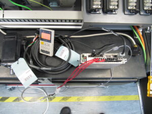
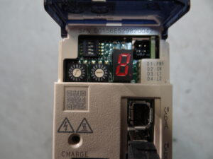
In this case, the unit involved was a Yaskawa SERVOPACK SGD7S-R90A20A. The device came to us with alarm A.EC8. According to the customer, the fault could still be acknowledged at first. The drive then ran again, but over a longer period it kept bringing the alarm back sporadically. Exactly this behavior is noticeable in practice, because at first it looks like an unstable limit condition and not like a complete failure. Fault patterns like this are often carried along in the machine for a long time because after a reset the drive appears to function again and the downtime initially remains manageable.
Over time, however, the behavior changed significantly. One day the alarm could no longer be reset. That meant a periodic fault had become a permanent failure. For the operator, the situation was critical because a replacement unit could in fact be sourced, but only with a lead time of more than five months and without reliable delivery assurance. At the same time, a retrofit was being proposed, which would have driven the costs for the entire machine up considerably. From a technical point of view, it was therefore clear that the focus was not only on troubleshooting the device, but also on restoring machine availability.
For classification of the fault code, it is important that A.EC8 is described in the available Sigma 7 documentation as Gate Drive Error 1. Yaskawa therefore assigns the fault to the gate drive circuit and states that if the alarm remains present after powering the unit off and on again, an internal defect in the SERVOPACK is the likely cause.
Incoming inspection and initial diagnosis
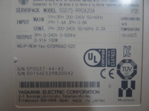
During incoming inspection, the unit was first checked externally. The nameplate showed a 200 to 240 volt unit with IP20, an output power of 100 watts, and a permissible ambient temperature range of minus 5 to plus 55 degrees Celsius. That fits a compact servo drive for smaller axes or auxiliary movements, where thermal reserve in the control cabinet still plays an important role.
The initial diagnosis focused on the fault behavior itself. The decisive point here was the history. An alarm that can still be acknowledged over a period of months and later remains permanently active usually does not point to a one time wiring fault. It would also be atypical for this to be purely an operating error. From a technical perspective, this pattern points much more to an internal fault that initially behaves at the limit under temperature changes, load changes, or increasing aging, and later fails in a stable manner. The fact that the fault ultimately could no longer be cleared confirmed this direction very clearly.
At the same time, it was ruled out that the cause was only a simple peripheral issue. With this kind of alarm, it would otherwise be expected that the fault would disappear permanently after a power reset or at least be reproducibly linked to external conditions. That was not the case here. Instead, the unit showed the typical progression from sporadic to permanent. That was the decisive finding for the further work.
Technical analysis
Technically, alarm A.EC8 points to the control section of the power stage. In this area, the power section is internally enabled and monitored. If a fault is detected there, the drive suppresses further motor actuation for protection reasons. This is safety relevant, because faulty switching states in the power stage can lead to consequential damage in the unit or to uncontrollable axis behavior. The available Yaskawa documentation accordingly describes A.EC8 as Gate Drive Error 1. If the alarm remains after a power reset, the SERVOPACK is evaluated as faulty.
In this case, the cause and effect chain was understandable. First, an unstable fault condition developed internally in the control section. That caused the monitoring to trigger intermittently, but the alarm could still be cleared. With continued loading and further aging, the borderline condition became a stable internal fault. The protective logic then responded permanently. For the operator, this looked like a sudden final failure, but technically it was the end of a damage process that had already been running for quite some time.
That is exactly why cases like this are tricky. The machine still appears to run, but the actual problem is already inside the unit. Especially in compact servo axes with frequent cycling, temperature changes, and densely populated control cabinets, it happens that an internal fault does not begin abruptly, but develops over many weeks or months. That also explains why the unit initially still functioned partially.
Repair measures and overhaul
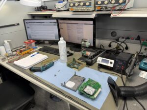
After the technical narrowing down, the SERVOPACK was opened, cleaned internally, and checked in the control and power path. This confirmed that the cause was not an external connection issue, but in the internal functional area of the unit. The repair was therefore carried out functionally in the affected control and power path. The goal was not only to eliminate the alarm, but also to reliably remove the unstable condition from the unit.
During the repair process, the drive was fully processed, the affected functional areas were overhauled, and the assemblies were checked for thermally and electrically critical points. In addition, preventive measures were implemented as they make sense for a servo drive that had been operating at the limit over a long period of time. This includes cleaning the entire interior, checking thermally stressed areas, and inspecting adjacent functional stages so that not only the current fault disappears, but operational reliability is also restored.
What mattered here was the clear distinction from a retrofit. The customer did not need a complete system change, but a technically sound restoration of the existing unit. That was exactly what was possible in this case.
Final functional test
After the repair, the SERVOPACK was tested on the test bench. The focus was on on off behavior, reliable enabling, start up behavior, and stability in continuous operation. Especially after an A.EC8 fault, it is crucial that the drive not only starts once, but also remains stable during repeated switching on, under load changes, and over thermal running time.
The test was carried out with repeated start stop cycles and operation across various load and speed ranges, insofar as this could be meaningfully represented for the available unit type. What was monitored in particular were fault free enabling, clean ramp up, signal stability, and behavior after warming up. The previously known alarm did not reappear during the test sequence. After the repair, the unit operated stably and reproducibly again.
Conclusion
This case shows a typical practical pattern with internal servo drive faults. An alarm that was initially still resettable became a permanent failure over time. Technically, the cause lay in the internal control section of the power stage, matching alarm A.EC8. Through the repair, the existing SERVOPACK could be retained and the long downtime of a spare parts route could be avoided. The repair is sustainable above all because not only was the acute alarm removed, but the unstable internal fault condition was technically eliminated and the unit was subsequently tested under realistic conditions.
Information about the mentioned Servopack: Yaskawa SGD7S-R90A20A AC Servopack
For more details about our Yaskawa repair services, visit: Yaskawa Sigma V Repairs
📞 Feel free to contact us if you have any questions about your Yaskawa drive technology!
Technical specifications
| Field | Value |
|---|
| Manufacturer | Yaskawa Electric Corporation |
| Device type | AC Servo Drive / SERVOPACK |
| Model designation | SGD7S-R90A20A |
| Series | Sigma 7 |
| Power | 100 W |
| Input voltage | Main supply 1PH/3PH 200 to 240 V AC, 50/60 Hz |
| Output voltage | 3PH 0 to 240 V AC, 0 to 500 Hz |
| Rated current | Output 0.91 A |
| Control type | digital servo control, closed loop control, exact version cannot be clearly derived from the available documents |
| Feedback | motor side feedback via servomotor/encoder, specific design in the present case not documented |
| Cooling | convection cooled, designed internally in the unit |
| Protection class | IP20 |
| Ambient temperature | minus 5 to plus 55 °C |
| Mounting | control cabinet mounting |
| Origin | Made in Japan |
| Product status | existing unit, spare parts supply in this specific case only available with very long delivery time |
Operating environment and possible applications
Typical machines include machine tools, handling axes, feed systems, smaller positioning axes, and auxiliary axes in automated systems. Based on the output power of 100 W, the specific unit is more likely to be used in the area of compact servo axes.
Typical years of manufacture for Sigma 7 applications are roughly the period from the mid 2010s onward. This should be understood here as an approximate classification, since the exact year of manufacture cannot be reliably derived from the available data.
Typical applications include positioning, indexing, feeding, clamping, auxiliary axes, format adjustment, and other controlled movements with high repeatability requirements.
Requirements for the environment and control cabinet are a clean dry environment, sufficient airflow, protection against oil mist, conductive dust, and condensation, as well as a stable power supply. In the documentation, Yaskawa also points out correct grounding, shielding, separate routing of power and signal lines, and sufficient discharge time after switching off.
Notes on thermal and electrical loading: Compact servopacks in particular react sensitively to poor control cabinet cooling, frequent start stop loading, and contamination that has built up over the years. This increases component temperatures and reduces internal reserve. Exactly these boundary conditions promote periodic fault patterns.
Functional description
Basic function: The SERVOPACK converts the mains supply into a controlled motor actuation and regulates the axis based on the feedback from the connected servomotor.
Interaction of power section, control, and feedback: The control calculates the target values, the power section implements them, and the feedback confirms position, speed, and movement status. Only this interaction creates the high dynamics and accuracy typical of servo axes.
Enable: Before movement can be enabled, the supply, internal self monitoring, and the relevant input signals must be plausible. In Sigma 7 variants with HWBB, the safety status is also monitored. If the safety jumper or the corresponding signal is missing, the drive will not release motor torque.
Protective logic: Internal protective functions monitor, among other things, the control section, power stage, and safety relevant signal paths. In alarm A.EC8, a fault in the gate drive circuit is detected. The alarm cannot be acknowledged as long as the cause remains present. If it remains after switching the supply off and on again, Yaskawa states that the SERVOPACK is likely defective.
Thermal monitoring: The unit must only be operated within its permissible temperature window. Thermal loading caused by tight control cabinets or deteriorated airflow has a direct effect on service life and fault risk.
Signal monitoring: In addition to the power stage, the inputs, feedback, and internal states are monitored. This prevents uncontrolled actuation in the event of internal faults.
Why these functions are safety relevant: Faults in the power section or in internal control must not lead to uncontrolled switching states. For this reason, the unit reacts to a detected internal fault with shutdown and alarm.
Alarm messages and troubleshooting
Note: In the provided, thematically relevant Yaskawa documents, only three specific alarm codes were documented for the uploaded Sigma 7 HWBB alarm section. To avoid mixing in foreign or invented codes, the table deliberately remains limited to these verifiable entries.
| Alarm code | Description | Possible cause | Recommended action |
|---|
| A.Eb1 | Safety Function Signal Input Timing Error | Time delay between /HWBB1 and /HWBB2 too large, fault in the signal path or wiring | Measure signal progression, check inputs and outputs, inspect wiring and connected safety chain |
| A.Eb1 | Alarm remains despite correction | Internal fault in the SERVOPACK | Replace or repair the unit |
| A.EC8 | Gate Drive Error 1 | Internal fault in the gate drive circuit | Switch supply off and on, if the alarm remains, the SERVOPACK is likely defective |
| A.EC8 | Alarm periodic, later permanent | Progressive internal fault condition | Inspect and repair the unit internally or replace it |
| A.EC8 | Alarm cannot be reset | Protective logic blocks while the cause is still present | Do not continue reset attempts in operation, carry out internal inspection |
| A.EC9 | Gate Drive Error 2 | Internal fault in the gate drive circuit | Switch supply off and on, if it recurs, inspect or replace the unit |
| A.EC9 | Alarm relevant on both axes in dual variants | According to the table, HWBB alarm applies to both axes | Carry out cross axis consideration on multi axis units |
| Hbb | No motor torque due to missing HWBB enable or missing safety jumper in HWBB variants | Safety jumper missing or safety device not connected correctly | Fit CN8 correctly or connect the safety device correctly |
| oo-oo | SERVOPACK System Error display | Internal system fault | Replace or repair the unit |
| Alarm general | Alarm remains after power cycle | Cause not eliminated or internal unit problem | Do not force enable, inspect the internal cause and technically assess the unit |
Assembly overview
| Assembly | Functional designation | Function | Notes for inspection or repair |
|---|
| Power section | Power stage | Supplies the motor with controlled output power | Check for internal fault patterns, thermal loading, and protective shutdowns |
| Control section | Gate drive area | Switches and monitors the power stage | Particularly relevant for A.EC8 and A.EC9, internal inspection required |
| DC link | DC supply section | Provides the internal energy for the power stage | Check for stable voltage conditions and thermal abnormalities |
| Control | Regulation and logic section | Calculates target values and processes feedbacks | Check function, enabling, and alarm behavior |
| Feedback interface | Motor feedback input | Processes the signals of the motor feedback | Check connector, cable, and signal stability |
| Safety section | HWBB / safety enable | Prevents motor torque without valid enable | Check CN8, safety jumper, or safety device correctly |
| Internal power supply | Auxiliary supply | Supplies logic and control sections | Also check in case of sporadic internal fault patterns |
| Cooling section | Heat dissipation | Keeps internal component temperatures within the permissible range | Check contamination, airflow, and thermal reserve |
| Connection section | Power and signal terminals | Safe electrical connection to the outside | Check for contact problems, locking, and loading |
| Monitoring | Protection and diagnostic path | Detects internal faults and triggers alarm | Evaluate alarm history and repeatability |