12.01.2026 by Viktor Siebert
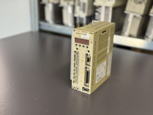
Repair of a Yaskawa Servopack SGDM-04ADY37 Ver. 10107-0 after a mains short circuit and Alarm 03
Initial situation and fault description.
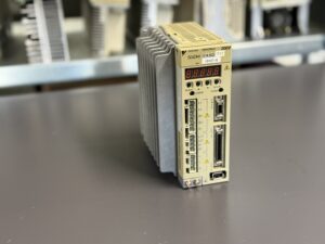
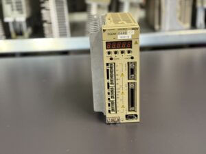
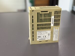
The Yaskawa Servopack SGDM-04ADY37 Ver. 10107-0 was sent in by the customer with the fault description “Alarm 03”. In addition, it was reported that a short circuit had previously occurred in the power supply network. At the time of receipt, it was not clear whether this mains fault had directly affected the servo amplifier. The machine had operated stably for a long period beforehand, and the fault occurred suddenly without any obvious warning signs.
Alarm 03 is considered a serious protection alarm in the SGDM series, as it indicates a fault in the power control or control logic area. Experience shows that such alarms can be triggered both by external influences such as mains disturbances and by internal aging processes. The objective of the inspection was therefore to clearly determine whether the unit was repairable and which assemblies were affected.
Incoming inspection and initial diagnosis
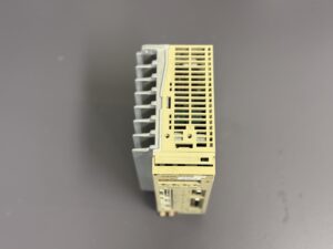
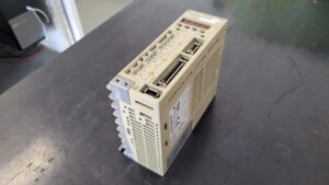
After the unit arrived, a complete visual inspection was carried out first. No burn marks or mechanical damage were visible from the outside. The connectors also showed no obvious abnormalities. The housing was then opened to allow a detailed internal inspection.
During the first measurements of the internal supply voltages, it became apparent that the control logic was no longer operating stably. The servopack could not be initialized reliably, and Alarm 03 was reproducible. Further measurements confirmed that parts of the control board were delivering incorrect reference values and that internal self-check routines could not be completed correctly.
Root cause analysis in connection with mains disturbances
A short circuit in the supply network represents a significant load for servo drives, even if upstream fuses or line filters are installed. In many cases, very short but high-energy voltage peaks occur. These can particularly affect sensitive components on the control board without causing immediately visible damage.
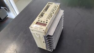
In this case, the power stage itself showed no abnormalities. The IGBT stages, DC link components, and the heatsink area were electrically and thermally sound. The fault was clearly limited to the control board. Due to internal damage in the logic and signal processing circuits, a component-level repair was no longer reasonable or technically reliable.
Decision to replace the assembly
After evaluating all measurement results, the decision was made to replace the complete control board. A partial repair would not have ensured long-term operational reliability. For this device type, a tested and compatible replacement control board is available that fully matches the SGDM-04ADY37 mechanically and electrically.
Before replacement, all existing parameters were backed up. Parameterization in these servopacks is closely matched to the specific machine, so complete parameter transfer is essential to avoid later commissioning issues.
Control board replacement and preventive overhaul
After removing the defective control board, the replacement board was installed and mounted correctly. The complete parameter set was then transferred. After successful initialization, the unit was tested again and powered up step by step.
As part of the repair, the servopack was additionally overhauled preventively. This included cleaning all internal assemblies, checking fan operation, inspecting thermally stressed connectors, and performing a general condition assessment of the power electronic components. The aim of these measures is to identify age-related weaknesses at an early stage and to extend the service life of the unit.
Functional testing and final inspection
After completion of all work, the SGDM-04ADY37 was operated on a suitable test setup. All relevant operating conditions were simulated, including power-up behavior, enable signals, load changes, and continuous operation. The servopack operated stably in all test phases without any renewed fault messages.
The alarm history remained empty, and the control response was clean and reproducible. After passing the final inspection, the unit was prepared for return shipment.
Conclusion
This repair case clearly demonstrates that external mains disturbances can cause serious internal damage even in robust servo drives. Control boards in particular are sensitive to voltage spikes. Through the targeted replacement of the affected assembly, clean parameter transfer, and a preventive overhaul, the Yaskawa Servopack SGDM-04ADY37 was fully restored. A structured diagnostic approach and a conservative repair strategy are essential for a sustainable solution.

Further information such as price and delivery time for: Yaskawa Servopack SGDM-04ADY37 Ver. 10107-0
More details about our Yaskawa repair expertise can be found here: Yaskawa SIGMA II repairs by Industrypart
📞 Please feel free to contact us if you have any questions regarding your Omron drive technology. Our experienced team is always available to assist you.
Technical specifications
| Feature | Value |
|---|
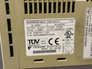
| Manufacturer | Yaskawa Electric |
| Model | SGDM-04ADY37 |
| Series | Sigma II |
| Version | 10107-0 |
| Input voltage | 200–230 V AC |
| Input phase | Single-phase |
| Output voltage | 0–230 V AC |
| Output phase | Three-phase |
| Rated power | approx. 0.4 kW |
| Rated output current | approx. 2.8 A |
| Protection class | IP1X |
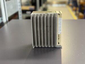
| Cooling | Forced air cooling |
| Country of manufacture | Japan |
Typical operating environment and applications
| Application area | Description |
|---|
| CNC machine tools | Feed axes |
| Special-purpose machines | Positioning and handling axes |
| Automation systems | Precise speed and torque control |
| Production equipment | Continuous operation with frequent load changes |
Alarm Messages and Troubleshooting Yaskawa SGDM-04ADY37 (Σ-II)
| Alarm code | Alarm name | Meaning | Typical cause | Recommended action |
|---|
| A.03 | Main Circuit Encoder Error | Abnormal detection data in the main circuit | Internal control logic fault, unstable internal power supply, damage to the control board | Check control board, replacement usually required |
| A.02 | Parameter Breakdown | EEPROM data is abnormal | Parameter loss due to voltage drop or aging | Initialize parameters, replace control board if the alarm recurs |
| A.04 | Parameter Setting Error | Parameter setting is outside the allowable range | Incorrect or corrupted parameter data | Check and reload parameters |
| A.05 | Combination Error | Servopack and servomotor capacities do not match | Incorrect motor to drive combination | Use a compatible servomotor and servopack |
| A.10 | Overcurrent or Heat Sink Overheated | Overcurrent detected or heat sink temperature too high | Short circuit, mains disturbance, defective power stage control | Check power stage and cooling system |
| A.30 | Regeneration Error Detected | Fault in regeneration circuit | Defective regenerative transistor or resistor | Check regeneration circuit |
| A.32 | Regenerative Overload | Regenerative energy exceeds capacity | Frequent braking, incorrect parameter settings | Review load profile and parameters |
| A.33 | Main Circuit Power Supply Wiring Error | Main circuit power supply wiring does not match settings | Incorrect mains wiring or configuration | Check and correct power supply wiring |
| A.40 | Overvoltage | DC bus voltage excessively high | Mains voltage spikes, excessive regeneration | Check mains quality and braking conditions |
| A.41 | Undervoltage | DC bus voltage too low | Voltage drop, unstable power supply | Check input power supply |
| A.71 | Overload: High Load | Short-term excessive load | Mechanical blockage or axis problem | Check mechanics and load conditions |
| A.72 | Overload: Low Load | Continuous excessive load | Incorrect axis sizing or constant overload | Review axis design and load |
| A.7A | Heat Sink Overheated | Heat sink temperature exceeded limit | Fan failure, clogged cooling paths | Check fan and clean cooling channels |
| A.bF | System Alarm | Internal system error | Control board failure | Replace control board |
| A.C9 | Encoder Communications Error | Communication with encoder is not possible | Encoder cable, encoder or logic fault | Check encoder circuit |
| A.F1 | Power Line Open Phase | One input phase missing | Power supply problem | Check mains power supply |
Main components
| Assembly | Function | Notes |
|---|
| Control board | Regulation and logic | Replaced in this case |
| Power module | Motor drive stage | Tested and found OK |
| DC link | Energy buffering | Preventively inspected |
| Fan unit | Cooling | Cleaned and tested |
| Interface board | Signal processing | Inspected |