15.05.2026 by Viktor Siebert
Production Downtime Caused by Yaskawa SGDB-10ANY11 Servopack with Alarm A.10 in a CNC Manufacturing Environment
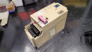
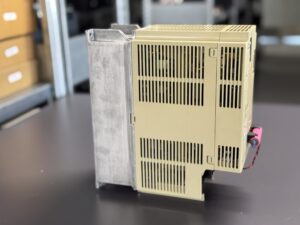
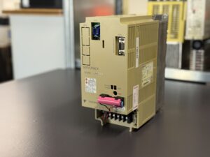
A Yaskawa SGDB-10ANY11 Servopack was sent to our workshop from an active CNC production line after one axis suddenly stopped during operation. The machine operator reported a recurring A.10 alarm immediately after servo activation. The affected machine could no longer complete its homing sequence, causing the entire machining line to stop.
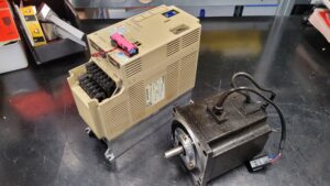
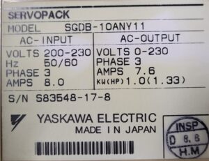
The installed Servopack belongs to the Yaskawa SGDB series and is designed for 200 to 230 VAC three phase input power and an AC servo motor with 1.0 kW output power. According to the nameplate, the unit operates with 7.6 A output current and a three phase motor output.
Introduction as a Real Service Case
The customer operates several CNC machining centers within an automated production environment. During the early production shift, a feed axis suddenly failed. Alarm A.10 remained active on the operator panel. Multiple restart attempts were unsuccessful. Since the axis could no longer be enabled, the complete manufacturing process stopped.
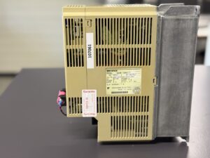
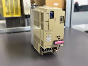
The affected servo drive was immediately shipped for urgent diagnostics. During incoming inspection, it became clear that the unit had operated for years in a thermally stressed environment. The ventilation channels were contaminated with oil saturated dust, and the housing showed clear signs of long term industrial operation.
The Yaskawa alarm table identifies alarm A.10 as an Overcurrent fault.
Initial Diagnosis
Several abnormalities were already visible during visual inspection:
- discoloration around the power stage
- thermally stressed solder joints near the power modules
- aged electrolytic capacitors in the DC bus
- heavily contaminated heatsinks
- conductive oil residue near the gate driver section
According to the Yaskawa documentation, alarm A.10 corresponds to an Overcurrent condition that occurs when the current inside the main circuit exceeds the allowed threshold.
The manual additionally states that overcurrent conditions are frequently related to defective power transistors, motor connection problems, or current feedback failures.
Electrical input measurements showed:
- DC bus voltage present
- control section stable
- power stage not enabling
- immediate overcurrent trip when servo ON was activated
Actual Root Cause
After complete disassembly and laboratory analysis, the root cause was clearly identified.
The following assemblies were defective:
- failed power transistor inside the main power stage
- thermally damaged gate driver circuitry
- aged DC bus capacitors with elevated ESR
- partially oxidized motor power connectors
- thermally stressed current sensing paths
The failure chain most likely developed over years of thermal overload:
- contaminated cooling reduced heat dissipation
- elevated temperatures permanently stressed the IGBT module
- DC bus capacitors lost capacitance
- current peaks increased
- power transistor switching became unstable
- Overcurrent protection A.10 was triggered
This behavior matched the protection descriptions found inside the Yaskawa service manual.
Repair Measures
After complete disassembly, the following repair work was performed:
- replacement of defective power modules
- replacement of stressed gate driver components
- replacement of aged electrolytic capacitors
- complete cleaning of cooling channels
- reworking thermally stressed solder joints
- insulation testing of all power stages
- verification of current sensing amplifiers
- cleaning of all connectors
- replacement of thermal interface materials
- inspection of the internal dynamic brake circuit
The Servopack was then fully tested under load conditions.
The load simulation included:
- dynamic load changes
- acceleration cycles
- thermal stress testing
- long duration full current operation
- monitoring of current regulation
- monitoring of DC bus stability
Final Testing and Return Shipment
After the repair was completed, the Yaskawa SGDB-10ANY11 Servopack was tested on a dedicated servo drive test bench under realistic operating conditions.
The following tests were performed:
- servo enable functionality
- stable current regulation
- dynamic load response
- thermal stability
- encoder feedback integrity
- protection circuit verification
- proper overcurrent protection behavior
Alarm A.10 no longer occurred after repair. The axis could again perform stable homing and continuous operation under load.
After successful final testing, the repaired unit was returned to the customer using express industrial service shipping.
Customer Feedback
“The axis immediately returned to stable operation after reinstalling the unit. The fast repair turnaround was extremely important because the machine had to return directly into production.”
Further details on our Yaskawa repairs can be found here: Yaskawa Sigma 1 Repair
📞 Feel free to contact us if you have any questions regarding your Yaskawa drive technology. Our team will be happy to assist you.
Technical Specifications
| Parameter | Value |
|---|
| Manufacturer | Yaskawa Electric |
| Model | SGDB-10ANY11 |
| Device Type | AC Servopack |
| Input Voltage | 200 to 230 VAC |
| Input Frequency | 50/60 Hz |
| Input Phases | 3 Phase |
| Input Current | 8.0 A |
| Output Voltage | 0 to 230 VAC |
| Output Phases | 3 Phase |
| Output Current | 7.6 A |
| Output Power | 1.0 kW |
| Motor Power | 1.33 HP |
| Control Method | Transistorized PWM Control |
| Feedback System | Optical Encoder |
| Protection Functions | Overvoltage, Overcurrent, Overspeed, Overload |
| Dynamic Brake | Integrated |
| Cooling | Heatsink / Self Cooling |
| Mounting Type | Base Mounted |
Technical values from manual and nameplate.
Operating Conditions
| Parameter | Specification |
|---|
| Ambient Temperature | 0 to 55°C |
| Storage Temperature | -20 to +85°C |
| Humidity | max. 90 % non condensing |
| Vibration Resistance | 0.5 G / 2 G |
| Mounting | Vertical |
| Environmental Protection | Free from oil mist and conductive dust |
| Cooling Requirement | Sufficient air circulation required |
Cooperation with Other Equipment
According to the documentation, the Yaskawa SGDB-10ANY11 supports several Yaskawa servo motor series:
- USAMED series
- USAFED series
- USASEM series
- USADED series
Supported feedback systems:
- 6000 pulse encoder
- 5000 pulse encoder
- 4000 pulse encoder
Supported interfaces:
- Optical Encoder Feedback
- PG Output
- Torque Monitor
- Speed Monitor
- Servo ON
- Current Limit Input
- Position Output
Functional Description
The SGDB-10ANY11 Servopack is a transistorized PWM servo drive designed for industrial machine tools and CNC applications.
The unit handles:
- speed regulation
- current regulation
- position feedback
- overcurrent protection
- overvoltage protection
- dynamic braking
- encoder signal processing
Feedback is provided through optical encoders with different pulse resolutions. The internal regulation continuously processes current, speed, and position signals in real time.
Integrated protection functions include:
- Overcurrent Detection
- Overload Detection
- Overspeed Protection
- Regeneration Error Detection
- Heat Sink Overheat Detection
- Open Phase Detection
Alarm and Error Codes
| Alarm | Error Name | Meaning | Reset | Corrective Action |
|---|
| A.10 | Overcurrent | Excessive current in main circuit | Power Reset | Inspect power stage |
| A.20 | Blown Fuse | Main fuse triggered | Service | Check power modules |
| A.30 | Regeneration Error | Brake circuit failure | Reset | Check regeneration stage |
| A.40 | Overvoltage | DC bus voltage too high | Reset | Check input voltage |
| A.51 | Feedback Overspeed | Speed exceeded limit | Reset | Check encoder |
| A.70 | Overload | Overload detected | Reset | Reduce axis load |
| A.71 | Overload | Momentary overload | Reset | Check load behavior |
| A.72 | Overload | Continuous overload | Reset | Inspect cooling and motor |
| A.81 | Heat Sink Overheat | Heatsink overheating | Cool Down | Check ventilation |
| A.C1 | Overrun | Regulation error / overrun | Reset | Check encoder and regulation |
| A.F1 | Open Phase | Missing supply phase | Reset | Check power supply |
| CPF00 | Digital Operator Error | Operator communication error | Reset | Inspect operator panel |
Main Assemblies
| Assembly | Function | Typical Failure |
|---|
| Power Stage | Motor current regulation | IGBT failure |
| DC Bus | Voltage stabilization | ESR increase |
| Gate Driver | Power module switching | Switching faults |
| Control PCB | Regulation and monitoring | Communication failure |
| Current Sensing | Overcurrent detection | Offset faults |
| Heatsink | Heat dissipation | Overheating |
| Encoder Interface | Position feedback | Signal loss |
| Dynamic Brake | Emergency braking | Regeneration faults |
Preventive Measures for the Customer
The following maintenance procedures are recommended for long term reliability:
- regular heatsink cleaning
- inspection of airflow channels
- connector inspection
- DC bus capacitor checks
- thermal imaging under load
- grounding verification
- insulation testing of motor cables
- replacement of aged cooling fans
- inspection for oil mist and conductive contamination
Especially in older servo drives, insufficient cooling frequently causes power stage failures and overcurrent alarms.
Conclusion
Alarm A.10 on this Yaskawa SGDB-10ANY11 was caused by a thermally damaged power stage. Through complete refurbishment of the power section and restoration of thermally stressed assemblies, the Servopack was successfully returned to stable operation.
Regular maintenance and cleaning prevent many of these failures before they lead to costly production downtime.