01.10.2026 by Viktor Siebert
Yaskawa CACR-SR15BE12G-E: Blank Display and No Connection to the Z Axis
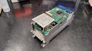
When the machine was switched on, the display on the Yaskawa CACR-SR15BE12G-E Servopack remained blank. The customer also reported that there was no connection to the Z axis. The unit was therefore sent to industrypart for inspection and repair. This type of failure affects a central machine function: without an operational servo amplifier, the associated axis cannot be controlled normally.
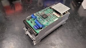
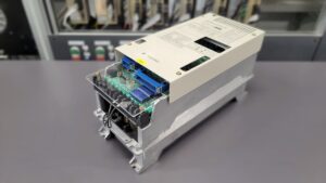
The pictures before and after repair, together with the test bench recording, document this case. In the test video, the connected unit’s display is active again. This article explains the symptoms and the relevant diagnostic and testing steps. Individual replacement components are not listed because no reliable information about them has been provided.
What Does the Servopack Do?
The CACR-SR15BE12G-E is a Yaskawa servo amplifier. It supplies and controls the associated servomotor. The power electronics, control circuitry and motor feedback work together. Only when these elements and the required enable signals are correctly coordinated can a command from the machine controller produce controlled axis movement.
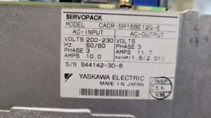
The nameplate specifies a power rating of 1.5 kW, a three-phase input of 200–230 V at 50/60 Hz and an input current of 10.0 A. The three-phase output is rated at 11.7 A. These details help identify the unit and establish a suitable test setup. However, they do not replace checking the full device variant and the connected motor and control equipment.
Why a Blank Display Is Not a Definitive Diagnosis
A blank display is initially a symptom. It proves neither a motor failure nor a defect in the power transistors. Possible causes include a missing external control supply, an internal power supply fault or a problem in the control electronics. The connections between the supply, control board and display also need to be examined.
Here, “no connection to the Z axis” is the customer’s description. It does not establish a particular bus system or a specific communication alarm. If the Servopack electronics fail to start, ready signals or other expected feedback may also be absent. The first step is therefore to establish whether the amplifier starts up correctly at all.
Systematic Checks from the Connections to the Control Board
For these symptoms, a meaningful incoming inspection begins with accurate device identification and a visual examination. This includes the terminals, connectors, circuit boards and visible components. Discolouration, damaged contacts or suspect solder joints may provide clues. However, an unremarkable external appearance does not rule out an electrical fault.
The supply is then checked using the appropriate connection documentation. The main power supply and the control electronics supply must be considered separately. If the specified supply is present at the unit, the next step is to check whether the internal voltages are generated and remain stable. A short-circuited load can cause a supply to collapse just as a fault within the power supply itself can.
Only then can the investigation be narrowed down to individual circuit sections. Relevant aspects of the control board include its power supply, logic initialisation and display connections. Diagnosis requires comparing measurements with the documentation for the specific hardware revision. Simply replacing suspected ageing components is no substitute for these checks.
Assembly Design and Repair
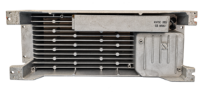
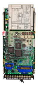
The component list supplied for this unit identifies one CACR-SR1B control board, one CACR-F2TBI-E power board and one power stage. The photographs also show the display and operating buttons, connectors and the rear heat sink with a power resistor. The modular construction helps distinguish control functions from power functions during inspection.
Our general repair service for the CACR-SR series includes cleaning, replacement of defective or worn components as required, parameter checks and test bench inspections. Which components are replaced in an individual unit depends on the findings. For the CACR-SR15BE12G-E shown here, no individual component replacement details are available. It would therefore be incorrect to present a capacitor, transistor or power supply replacement as a confirmed repair operation.
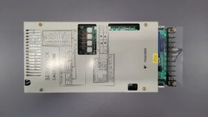
The pictures after repair show the unit both with its cover fitted and with the control board and heat sink visible. They provide a record of the condition of the assemblies. However, the electrical quality of a repair is assessed through testing, rather than solely from clean surfaces or an apparently complete assembly.
Testing on the Test Bench
The available video shows the Servopack connected on the test bench. Its display is illuminated, and the motors in the test setup and an operator panel for Yaskawa CACR-SR drives can also be seen. This documents an active display at the test bench. The recording provides an insight into the setup but does not replace a complete test report.
A comprehensive final test considers startup, enable signals, feedback, the response to changes in the command value and the behaviour of the connected drive. Depending on the symptoms, repeated power cycling and behaviour as the unit warms up also need to be assessed. These checks establish whether the supply and control electronics remain stable during operation and whether the fault recurs.
The exact test duration, load values and final measurement results have not been provided for this case. A load test lasting several hours is therefore not inferred from the short video. Nor does the recording confirm that the customer’s machine has already been recommissioned.
Operating Advice
If the display becomes blank again, the complete situation should be recorded: does the fault occur immediately at power-up or only after extended operation? Are other axes affected? What message does the machine controller display? This information helps distinguish a shared supply problem from a fault in an individual Servopack.
Clean ventilation paths, intact connectors and a suitable control cabinet environment support reliable operation. Checks on opened units and power supplies must be performed by qualified personnel. Before work begins, the equipment must be isolated and stored energy discharged in accordance with the relevant manufacturer’s instructions.
From Symptoms to Documented Testing
This case illustrates why the supply and electronics startup must be investigated first when the display remains blank. The missing connection to the Z axis is an important clue, but it does not identify the faulty assembly on its own. Together with targeted diagnosis and appropriate functional testing, pictures before and after repair provide a traceable record of the unit.
Price, Lead Time and Further Information
Current information on the price and lead time of the Yaskawa CACR-SR15BE12G-E Servopack, product ID 4511 can be found on the corresponding product page.
Further information about our repair services for Yaskawa CACR-SR Servopacks is available in our service section.
📞 Please feel free to contact us with any questions about your Yaskawa drive technology. Our team will be pleased to assist with the technical assessment, repair and testing of your unit.
Technical Specifications
| Feature | Technical information |
|---|
| Manufacturer | Yaskawa Electric |
| Model | CACR-SR15BE12G-E |
| Alternative search spelling | CACR-SR15BE12GE; verify the complete variant before replacement |
| industrypart product ID | 4511; not a manufacturer order number |
| Device type | Servopack, AC servo amplifier |
| Associated axis in this customer case | Z axis according to the fault description |
| Power rating on the nameplate | 1.5 kW / 2.01 HP |
| Input | 200–230 V AC, 3 phases |
| Input frequency | 50/60 Hz |
| Input current | 10.0 A |
| Output | 3 phases; 11.7 A according to the nameplate |
| Output voltage | 0–230 V according to the product page; not entered on the supplied nameplate |
| Heat dissipation | Heat sink visible in the photographs; no confirmed information about an internal fan |
| Country of manufacture | Japan |
| Motor and CNC controller | Specific types not provided for this customer case |
| Year of manufacture, weight, dimensions | No confirmed information available |
| Documentation reference on the unit | Bulletins TSE-S800-11.1 / -11.2 for parameters, monitoring and alarm traceback |
Operating Environment and Compatible Equipment
In this customer case, the Servopack was assigned to a machine’s Z axis. The machine manufacturer, CNC type and motor model have not been specified. Compatibility with a particular motor or CNC controller is therefore not confirmed. Before replacement, compare the complete model designation, board revisions, interfaces, motor and encoder variants, and parameters. Matching power ratings alone are not sufficient to approve a replacement.
Functional Description
The amplifier converts the electrical supply into a controlled three-phase motor current. The control electronics process command values, enable signals and feedback, and operate the power electronics. Monitoring functions detect current, voltage and operating faults, among other conditions. The display and operating buttons provide status information and access to device-specific functions. The precise signal and interface arrangement must be taken from the documentation for the relevant variant.
Components
The designations and quantities of the three main assemblies are taken from the supplied internal component list. Additional visible elements are listed separately and are not counted as additional complete assemblies.
| Assembly | Designation on board or module | Quantity | Function | Inspection or repair notes |
|---|
| Control board | CACR-SR1B | 1 | Control, signal processing and display | Check supply, connectors and startup behaviour |
| Power board | CACR-F2TBI-E | 1 | Power section circuitry | Designation from the component list; verify against the original before replacement |
| Power stage | No separate designation provided | 1 | Power conversion for the motor | Check for short circuits and perform electrical checks appropriate to the circuit |
| Visible power resistor | RH70C, 30ΩJ, GB IWAKI | 1 visible | Power resistor; verify its exact circuit role using the schematic | Check resistance, connections and thermal condition |
| Heat sink | No separate designation provided | 1 visible | Heat dissipation | Check surfaces, cooling paths and thermal interfaces |
Alarm Messages and Troubleshooting
The following table uses the short alarm designations directly from the photographed device legend. The final column contains general diagnostic approaches, not verbatim manual instructions. None of these codes was reported as an alarm actually displayed in this repair case.
| Code on device legend | Original designation | Technical meaning | General diagnostic approach |
|---|
| A0 | Communication Error | Communication fault | Check supply, interfaces and associated connections |
| A1 | Over Current | Overcurrent | Inspect motor cable, motor, power stage and current sensing |
| A2 | MCCB Trip | Circuit breaker trip | Investigate the cause of the trip and the main power supply; do not repeatedly switch on without investigation |
| A3 | Regenerative Trouble | Regenerative circuit fault | Examine braking or regenerative circuitry and connections |
| A4 | Over Voltage | Overvoltage | Check the supply and energy absorption during deceleration |
| A5 | Over Speed | Overspeed | Check feedback, wiring and controller settings |
| A6 | Under Voltage | Undervoltage | Check the supply, voltage dips and internal sensing |
| A7 | Over Load | Overload | Examine mechanical load, current and parameter settings |
| A8 | Reference Point Error | Reference point fault | Check reference signals and the appropriate encoder/controller documentation |
| A9 | A/D Error | Analogue-to-digital conversion fault | Examine the electronics supply and signal processing |
| AC | Over Run | Overrun fault | Check feedback and wiring using the exact manual |
| AF | Open Phase | Phase loss | Check supply phases and connections |
The additional supplied excerpts named “Alarme 1” and “Alarme 2” use more detailed indications such as A.10 and A.20. Without a confirmed match between manual and device variant, these are not equated with the short front-panel codes. The CACR-SR..BB manual also supplied does not establish applicability to the BE variant discussed here.
Diagnostic Notes on the Main Fault
| Aspect | Assessment for this case |
|---|
| Customer report | Display blank at power-up; no connection to the Z axis |
| Alarm code actually reported | None |
| Possible external cause | Missing or incorrect supply, connection problem |
| Possible internal cause | Fault in the internal supply, control board or display connection |
| Appropriate test sequence | Identification and visual inspection, external supply, internal supply, controller startup, interfaces and function |
| Distinction | A blank display is neither automatically A0 nor evidence of a motor fault |
| Documented later condition | Connected unit with an active display in the test video |
| Not documented | Specific defective component, replacement list, load values, test duration and recommissioning at the customer’s site |
Preventive Measures
- Inspect and professionally clean the control cabinet, air paths and heat sink according to environmental conditions and operating hours.
- Have connectors, terminals and cables checked for secure attachment, damage and signs of overheating.
- Investigate recurring startup problems or temperature-dependent failures promptly.
- Record existing parameters and the complete device designation; create backups only using the specified procedure.
- When a fault occurs, record the behaviour of the display, machine controller and other axes together.
Image Captions and Alt Text
| Image | Caption / alt text |
|---|
| Before repair 1 | Yaskawa CACR-SR15BE12G-E before repair with the control board and connection terminals visible |
| Before repair 2 | Yaskawa Servopack before repair from a second viewing angle |
| After repair 1 | Yaskawa CACR-SR15BE12G-E after repair with the cover fitted |
| After repair 2 | Front view of the Yaskawa Servopack after repair |
| After repair 3 | Heat sink and power resistor after repair, background removed |
| After repair 4 | Control board and operating unit after repair, background removed |
| Test video | Yaskawa CACR-SR15BE12G-E connected at the industrypart test bench with an active display |