26.02.2026 by Viktor Siebert
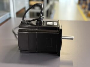
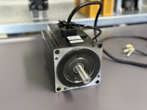
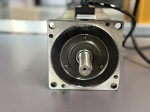
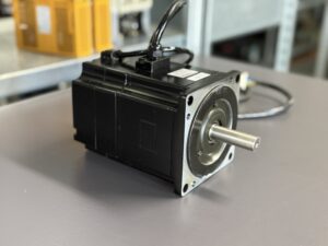
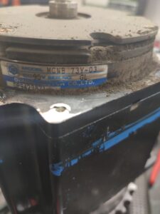
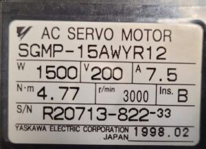
Repair of a Yaskawa SGMP-15AWYR12 servo motor: holding brake without holding torque and intermittent feedback errors due to abrasion
Initial situation and symptom description
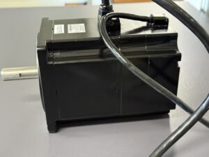
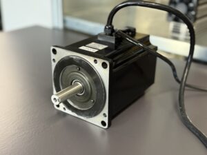
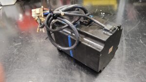
A Yaskawa AC servo motor SGMP-15AWYR12 with an integrated holding brake arrived from a system in which the axis could no longer be held safely at standstill. After switching off the servo enable, the load did not remain in place but drifted away. In addition, feedback errors occurred repeatedly, sometimes directly after switching on, sometimes during slow movements. The fault was often time-related to stopping and re-enabling. Conspicuous was the combination of missing holding function and unstable position feedback, because both functions are closely coupled within the same motor assembly.
Incoming inspection and first diagnosis
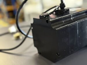
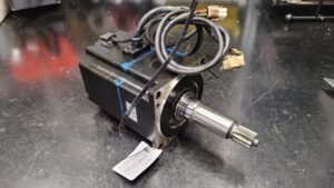
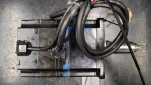
Before any work, the unit was de-energized, secured against being switched on again, the discharge time was observed, and absence of voltage was verified. Incoming inspection was followed by a visual check of housing, connectors, and cable entry. From the outside, no thermal discoloration was visible, but fine dust was visible escaping in the brake area. The shaft could be turned, but it felt rough and uneven. On the test bench with an SGDB-15ADG servo amplifier, the motor was first tested in the low speed range. Sporadic feedback faults were reproducible. The holding brake was controlled separately, and the closing effect was clearly reduced. An insulation test of the motor winding to the housing showed unremarkable values in the range of approx. 100 MΩ at 500 V DC.
Technical analysis
The holding brake in such servo motors is typically spring applied and is electrically released. It is designed as a wear function and reacts sensitively to frequent switching cycles, vertical loads, and incorrect sequences, for example when the brake engages under speed. In that case, friction energy is generated, the friction material overheats and can break down into fine abrasion. This abrasion is distributed by air movement and motion inside the motor. If it reaches the position feedback system, it can disturb optical or magnetic signals, which leads to dropouts, phase faults, or communication interruptions. At the same time, abrasive dust can enter the bearing system, damage the raceway and thereby cause rough running, increased friction, and additional thermal load. The cause effect chain here is: an overloaded or worn brake generates abrasion, abrasion contaminates feedback system and bearing system, and this results in missing holding force and sporadic feedback alarms.
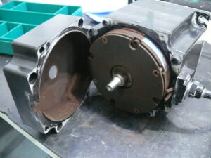
Repair measures and refurbishment
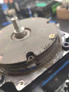
After opening the motor, the suspicion was confirmed: there was a very large amount of abrasion in the brake area, the friction material had almost completely disintegrated and was distributed throughout the entire motor. The position feedback system was mechanically damaged and electrically no longer stable. The bearing system also showed clear running marks and rough operation. To achieve a sustainable refurbishment, a complete overhaul was carried out. This included full internal cleaning, replacement of the functional brake assembly, replacement of the feedback assembly, renewal of the bearing system, and renewal of the affected sealing and protective points. The winding was electrically checked, cables and connectors were reworked, and the brake was adjusted with the correct release and closing clearance. As a preventive measure, it was recommended to check the brake control in the machine, in particular switching times, delays, and avoiding braking under speed, as well as to regularly check cabinet cooling and filters.
Final functional test
The functional test was carried out on the test bench with regulated supply, current and voltage measurement, as well as load simulation via the servo amplifier. Measurements on live parts were carried out exclusively by a qualified electrician with suitable equipment and according to local rules. Start and stop behavior, reference run, low speeds, medium speeds, and high speeds up to the rated range were tested. In addition, brake cycles at standstill and after defined deceleration were carried out in order to verify the holding function reproducibly. Protective functions such as current limiting, temperature monitoring, and feedback signal monitoring were logged. Result: the motor ran smoothly, the feedback remained stable without fault messages, and the holding brake closed reliably. The test was fault free, stable, and reproducible.
Conclusion
The failure was caused by massive wear of the holding brake with subsequent abrasion contamination. This caused holding force and feedback signal quality to be lost at the same time, which manifested as standstill drift and recurring feedback errors. Through complete cleaning, replacement of the affected functional assemblies, and subsequent test bench testing, the repair is technically sustainable because the cause, secondary damage, and adjustment points were addressed together.
Information about the mentioned Servopack and Servomotor:
More information about our Yaskawa repairs can be found here.
📞 Feel free to contact us if you have any questions regarding your Okuma drive technology. Our experienced team is always ready to provide you with expert advice and support.
Technical specifications
| Field | Value |
|---|
| Manufacturer | Yaskawa |
| Device type | AC servo motor with integrated holding brake, release voltage approx. 90 V DC |
| Model designation | SGMP-15AWYR12 |
| Series | SGMP |
| Power | approx. 1.5 kW |
| Input voltage | Supplied by servo amplifier, typically approx. 3 x 200 V AC, PWM |
| Output voltage | not applicable, mechanical torque output |
| Rated current | approx. 8 A RMS, depending on amplifier and parameter settings |
| Control type | field oriented control in the servo amplifier, sine PWM |
| Feedback | incremental encoder, A B Z, resolution approx. 2500 pulses per revolution |
| Cooling | natural convection via housing, depending on installation and airflow |
| Degree of protection | approx. IP54, depending on version and connector system |
| Ambient temperature | approx. 0 to 40 °C |
| Mounting | flange mounting, coupling or belt drive depending on the machine |
| Origin | unknown |
| Product status | likely discontinued |
Operating environment and possible applications
Typical machines are machine tools, handling systems, packaging machines, printing and paper systems, as well as special purpose machines with controlled axes. Common years in the field, depending on the machine, are approx. 1995 to 2005. Applications include positioning, cycle operation, infeed motions, auxiliary spindle functions, and vertical axes with holding requirements.
For operation, stable cabinet cooling, clean airflow, and a clear separation of power cables and signal cables are important. High ambient temperatures, clogged filters, and stalled fans increase the thermal load on motor, brake, and feedback system. In addition, power quality and grounding affect the signal margin of the feedback system, especially with long cable runs or unfavorable shielding.
Functional description
The servo motor converts the current and torque demand specified by the servo amplifier into motion. The power stage in the amplifier generates a pulsed three phase voltage, the control builds field oriented current control from it and stabilizes torque and speed. The position feedback system provides angular position and speed information as an A B Z signal to the amplifier so that positioning accuracy and dynamics are achieved.
The integrated holding brake is a safety relevant function for standstill states. It is normally electrically released and closes without voltage by spring force. Enable logic, protective logic, thermal monitoring, and signal monitoring work together: if implausible feedback or overcurrent is detected, the drive is switched off, the machine must ensure a safe axis reaction, and the brake should hold the standstill. These functions are safety relevant because incorrect behavior can lead to uncontrolled motion, especially on vertical axes.
Alarm messages and troubleshooting
| Alarm code | Description | Possible cause | Recommended action |
|---|
| A.00 | Absolute Encoder Data Error, only in absolute operation | Feedback system delivers invalid data, disturbance in cable or sensor | Check feedback system and cable, check parameters, replace feedback assembly if required |
| A.01 | Absolute Encoder Data Error, only in absolute operation | Supply voltage to feedback system unstable, contact issue | Check connectors, check shielding and grounding, have supply measured by a qualified electrician |
| A.10 | Overcurrent | Short circuit, mechanical jam, incorrect parameter setting | Check mechanics, check cable and insulation, validate parameters, test amplifier and motor separately |
| A.30 | Regeneration Error | Regeneration too high, regeneration path or DC link issue | Check regeneration path and DC link, check motion profiles and deceleration ramps |
| A.31 | Overvoltage | Mains voltage too high, too hard deceleration, regeneration | Check mains quality, adjust deceleration ramps, check amplifier DC link |
| A.40 | Main Circuit Voltage Error | Undervoltage, phase fault, unstable supply | Check supply, protective devices, switching devices, and phases, measurements only by qualified electrician |
| A.51 | Feedback Overspeed | Feedback system faulty, wrong parameters, signal disturbance | Check feedback signal, check shielding, check parameters and limits |
| A.70 | Overload | Continuous load too high, axis stiff, bearing system damaged | Check mechanics, check lubrication and guides, check motor run, adapt load profile |
| A.72 | Overload, Continuous overload | thermal overload due to continuous cycling or high holding torques | Check cooling, check cycle, check motor and brake for wear |
| A.C2 | Encoder Phase Detection Fault, only in incremental operation | A B Z phase relation implausible due to contamination or feedback defect | Check cable and connectors, check signal quality, replace feedback assembly |
| A.C3 | PG phase disconnection of PG signal line | Interruption or intermittent contact in feedback cable | Check strain relief, connectors and cable, check shield contact |
| A.C4 | PC Disconnection | Interruption between amplifier and operator or interface | Check wiring and interface, check contact quality |
| A.63 | Momentary Power Loss Error | short supply dips, switching devices or supply unstable | Check supply and switching devices, evaluate event log, assess mains quality |
| A.C7 | Power Supply Line Open Phase | Phase loss or defective protective device | Check phases and protective devices, measurements only by qualified electrician |
Module overview
| Module | Functional designation | Function | Notes for inspection or repair |
|---|
| Power connection and insulation | Energy feed into the motor | Transfers PWM three phase energy from the amplifier | Insulation test to housing only with amplifier disconnected, visual check for oil and chafing points |
| Electromagnetic conversion system | Torque and motion function | Converts electrical power into torque | Phase resistance comparison, thermal check under load, noise and vibration check |
| Position feedback system | Speed and position feedback | Provides A B Z signals for control | Check signal quality with suitable measuring equipment, observe shielding and grounding, rule out contamination |
| Holding brake | Standstill holding | Holds the axis at standstill without servo torque | Check release voltage and switching sequence, set mechanical clearance, consider wear with high switching frequency |
| Bearing and sealing system | Running quality and protection | Ensures smooth running and protects against ingress | Check roughness, axial play and temperature, clean sealing surfaces, eliminate sources of abrasion |
| Thermal protection and monitoring | Overtemperature protection | Reports overtemperature to the amplifier | Check cable path, plausibility versus ambient, do not bypass triggering |