18.02.2026 by Viktor Siebert
Repair of a Yaskawa Juspeed-F CIMR-22AS with internal power supply overheating and damaged PCB traces
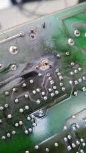
Overheated internal power supply with damaged PCB traces due to component drift.
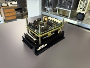
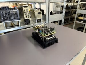
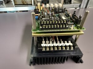
The Yaskawa Juspeed-F CIMR-22AS arrived at our workshop with the customer complaint that the drive was no longer regulating correctly and there was a noticeable burning smell in the control cabinet.
During the first power up on the test bench an unstable output voltage was observed. A slight burnt odor was clearly noticeable. The front LEDs did not show a clear blink code, which is typical for this analog generation.
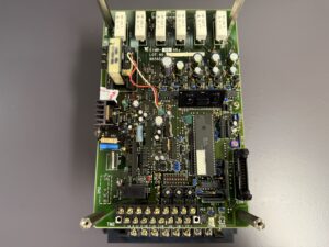
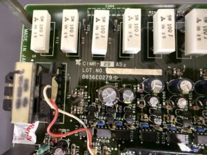
After opening the unit the suspicion was confirmed. In the area of the internal power supply several components were heavily thermally stressed. Resistors and electrolytic capacitors were clearly out of tolerance. This component drift caused increased current draw in the control circuit.
As a result the power supply section overheated. Several PCB traces were visibly darkened. Two traces had partially lifted from the substrate. The root cause was prolonged overcurrent due to aged components.
Repair steps included:
- Complete removal of the power supply board
- Cleaning of all thermally stressed areas
- Measurement of all resistors and capacitors
- Preventive replacement of all electrolytic capacitors
- Replacement of drifted resistors
- Reconstruction of damaged PCB traces using copper bridges
- Re soldering of all high current joints
Additionally:
- Fan replacement
- DC link capacitor inspection
- Power transistor testing
- Heat sink cleaning
Final testing included:
- 3 phase mains simulation
- 2.2 kW test motor
- Several hours thermal load
- Ramp function verification
- Load change simulation
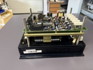
The unit ran stable without temperature rise in the power supply area. Output voltage remained constant.
After reinstallation at the customer site the inverter has been operating without faults.
Preventive Measures for the Customer
Recommended maintenance:
- Annual inspection of power supply board
- Fan replacement every 3 to 5 years
- Heat sink cleaning
- Terminal screw inspection
- Motor cable insulation test
- Replacement of electrolytic capacitors after 10 to 15 years
Benefits:
- Extended service life
- Avoidance of unplanned downtime
- Higher operational reliability
- Reduced maintenance costs
Conclusion
Even older analog drives such as the Yaskawa Juspeed-F CIMR-22AS can be technically repaired in a meaningful way. The internal power supply is a critical point after decades of operation. Preventive refurbishment significantly increases reliability and protects against production downtime.

Information about the mentioned Servopack and Servomotor:
- Yaskawa Juspeed-F CIMR-22AS
More information about our Yaskawa repairs can be found here.
📞 Feel free to contact us if you have any questions regarding your Yaskawa drive te
Technical Specifications
| Feature | Value |
|---|
| Voltage | 3 phase 200 to 230 V AC ±10 percent |
| Current | approx. 10 A at 2.2 kW |
| Power | 2.2 kW |
| Weight | approx. 12 kg |
| Dimensions | approx. 320 x 180 x 150 mm |
| Type | Analog transistor inverter VFD |
| Cooling | Fan cooled |
| Control | V f characteristic via potentiometer |
| Manufacturer | Yaskawa Electric |
| Production year | approx. 1985 to 1995 |
| Manual reference | Yaskawa Juspeed-F Series |
Application Environment and Compatible Equipment
The Yaskawa Juspeed-F CIMR-22AS is a classic analog frequency inverter from the 1980s and 1990s. It was widely used in machine tools, especially for auxiliary axes such as tool changers or magazine motors.
Typical applications:
- Automatic tool changers
- Coolant pumps
- Magazine and chain drives
- Auxiliary units in machining centers
Compatible with:
- 3 phase asynchronous motors 200 V class
- PLC controlled machines
- CNC systems from Matsuura, Mazak, Chiron and similar manufacturers
Functional Description
The CIMR-22AS operates using the classic V f principle. Motor speed is controlled proportionally to frequency while voltage is adjusted accordingly.
Key features of this generation:
- Analog speed reference
- No digital display
- Fault indication only via LED blink codes
- Internal rectification with power supply for control board
- Transistorized PWM power stage
The internal power supply generates auxiliary voltages for:
- Control logic
- Power transistor drive circuits
- Protection circuits
Typical protection functions:
- Overcurrent
- Overvoltage
- Undervoltage
- Overload
- Heat sink overtemperature
Alarm Messages and Troubleshooting
Typical fault patterns based on Yaskawa inverter logic and comparable servo documentation Converter Alarme CIMR_MR5-2
| Code | Description | Cause | Solution |
|---|
| Overcurrent | Overcurrent | Motor short circuit | Check motor and output |
| Overvoltage | DC bus too high | Braking energy | Extend decel time |
| Undervoltage | Undervoltage | Missing phase | Check mains |
| Overload | Overload | Mechanical jam | Check load |
| Heatsink | Overtemperature | Fan failure | Replace fan |
| Fuse | Fuse blown | Power transistor fault | Check power stage |
| DC Bus Fault | DC link fault | Power supply issue | Check PSU |
| Control Voltage | Control voltage error | Internal supply fault | Repair PSU |
| Regeneration Fault | Regenerative fault | Brake resistor | Check resistor |
| Open Phase | Phase loss | Mains problem | Check input |
Components
| Assembly | Designation | Function | Inspection Notes |
|---|
| Power supply board | Internal PSU board | Supplies control electronics | Measure capacitors |
| Power transistors | Early IGBT stage | Motor drive | Short circuit test |
| DC link capacitors | DC link caps | Energy storage | ESR measurement |
| Cooling fan | Cooling fan | Temperature control | Check rotation |
| Rectifier | Rectifier bridge | AC to DC conversion | Diode test |
| Control board | Control PCB | Logic and PWM | Check voltages |