01.10.2026 by Viktor Siebert
Yaskawa CIMR-MXN27P5: Alarm 65 and a short circuit in the power output stage
A Yaskawa CIMR-MXN27P5 inverter from a Star ECAS 20 sliding-headstock lathe arrived at industrypart with a fault that had become significantly worse within a few days. Initially, the machine repeatedly displayed “380500 profibus-dp: SP1 drive error, code 208”. Switching the machine off and on allowed it to start again each time. After approximately four to five days, the message changed to “380500 profibus-dp: SP1 drive error, code 65” at every power-up. The machine could no longer be started.
The inspection confirmed internal damage: there was a short circuit between motor output U and the positive pole of the DC link. The power output stage was repaired and the inverter underwent an extensive overhaul. The final test in our own Star ECAS 20 was successful.
The inverter’s role in the Star ECAS 20
The CIMR-MXN27P5 is part of the Yaskawa-Siemens drive system. In this application it is assigned to spindle drive SP1. It converts the DC-link voltage into a variable three-phase output voltage for the connected motor. The CNC commands the required operation; control, feedback and power electronics must work together.
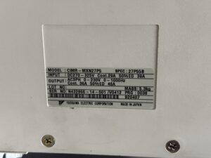
The nameplate specifies an input voltage of DC 270 to 325 V. The output is rated at three-phase 0 to 230 V and 0 to 1000 Hz. This is therefore an inverter supplied from the DC link. Its input ratings must not be interpreted as a direct three-phase mains connection. Distinguishing between the upstream converter and the downstream inverter is essential when diagnosing faults.
Why code 65 corresponds to drive alarm A.41
The CNC and the drive display the same fault code in different number formats. In the inverter alarm list of the relevant Yaskawa-Siemens manual, decimal CNC code 65 corresponds to hexadecimal drive code 0x41. The associated alarm is “Low-voltage” or “CNV low-voltage”, indicating undervoltage in the drive or converter context.
During the incoming test, our technician confirmed that CNC communication was working. However, A.41 appeared when the machine entered the ready state. This matches the final alarm number 65 reported by the customer. The message identifies the detected electrical condition. On its own, it does not identify a specific defective component.
The earlier code 208 is also listed in the same manual: decimal 208 corresponds to 0xD0 and means “Excessive position deviation”. This alone proves neither an encoder defect nor a definite link to the short circuit subsequently found. The sequence of customer-reported alarms remains relevant to the diagnosis, but it cannot replace an electrical inspection.
Distinguishing the PROFIBUS message from the actual fault
The machine’s message includes “profibus-dp”, which may initially suggest a communication problem. In this case, however, communication was working during the incoming test. The CNC was reporting a fault in the assigned spindle drive. The drive could communicate and still trigger an alarm when the machine was made ready.
A reliable diagnosis therefore requires the complete CNC message, the corresponding drive code and the measurement findings to be considered together. The available evidence would not have justified prematurely replacing the communication board. It would also be technically incorrect to call A.41 a “short-circuit alarm”: the relevant manual entry is undervoltage.
Incoming inspection with a clear finding
The electrical inspection revealed a short circuit from U to positive. U identifies one of the motor phase outputs; positive refers to the positive pole of the DC link. This finding directs the investigation towards the inverter’s power path. It must be distinguished from a purely software, parameter or bus-related fault.
A fault in the power section can, in principle, affect the electrical conditions of the DC link. However, no measurement record of the actual voltage during the original failure is available for this case. We therefore report the confirmed output-stage damage alongside the observed undervoltage alarm without claiming an undocumented internal sequence of events.
The documented incoming test also helped correlate the machine message with the drive response. A confirmed short circuit is not a reason to make further start attempts in production. Testing the DC link and power output stage requires an appropriately equipped specialist workshop.
Power output stage repaired and inverter extensively overhauled
The repair included restoring the power output stage and extensively overhauling the inverter. This went beyond simply resetting a fault message. The identified electrical damage was addressed during the repair; the unit then had to demonstrate correct operation together with a suitable machine.
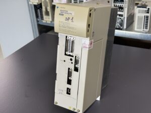
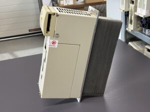
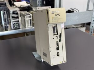
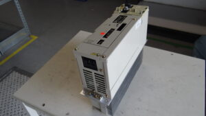
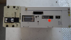
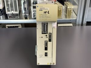
Pictures before and after the repair document the condition of the CIMR-MXN27P5. They complement the technical description but do not replace measurement or test results. Specific types of replaced semiconductors and a complete replacement list are not available for this report and are therefore not added.
Successful test in our own Star ECAS 20
industrypart operates a Star ECAS 20 as a test machine. Following repair and overhaul, the inverter was successfully tested in this machine environment. This step is particularly useful in a repair case of this type because it allows the interaction with the CNC and the installed drive system to be checked alongside the individual unit.
The successful final test is confirmed. A specific test duration, speed sequence or mechanical load has not been provided for this case. No particular endurance or full-load test is therefore inferred. The accompanying footage provides a brief view of the test and of the unit after the work was completed.
Investigating intermittent faults early
If a machine runs again after a restart, the underlying fault has not necessarily been resolved. In this case, repeated interruptions developed into a permanent standstill within a few days. Recording the complete alarm text, operating condition and frequency of occurrence from the first incidents is useful.
Preventive maintenance includes keeping cooling paths clear, maintaining effective cabinet cooling and checking connectors and power connections. The motor and cables should also be investigated where the evidence calls for it. These general measures do not establish that any particular maintenance issue caused the damage described here.
Outcome of the repair
Diagnosis of the Yaskawa CIMR-MXN27P5 from the Star ECAS 20 confirmed a short circuit between U and DC-link positive. CNC communication worked, while A.41 appeared when the machine was made ready. Following repair of the power output stage and an extensive overhaul, the test in our own machine was successful. This case shows why accurate alarm interpretation and electrical testing together provide the basis for a traceable repair.
Price, Lead Time and Further Information
Current information on the price and lead time of the Yaskawa CIMR-MXN27P5 inverter, item 37971 is available on the product page.
Further information about our repair services for Yaskawa-Siemens SGDK and CIMR drive systems is available in the relevant service section.
Please contact us if you have questions about your Yaskawa drive technology or a specific fault. Our team will assist you with the technical assessment, repair and testing of your unit.
Technical Specifications
| Feature | Technical information |
|---|
| Manufacturer | Yaskawa Electric Corporation |
| Model | CIMR-MXN27P5 |
| Nameplate specification | 27P55B |
| Nameplate program identification | PRG 0038 |
| Device type | Inverter / Spindle Drive |
| Input voltage | DC 270–325 V |
| Continuous input current | 29 A |
| Input current at 50% duty | 39 A |
| Output voltage | AC 3PH, 0–230 V |
| Output frequency | 0–1000 Hz |
| Continuous output current | 36 A |
| Output current at 50% duty | 46 A |
| Mass | 5.3 kg |
| Country of manufacture | Japan |
| Application in this case | Star ECAS 20, spindle drive SP1 |
| Power classification | 7.5 kW class; manual lists CIMR-MXN27P55A. This unit carries SPEC 27P55B; electrical values above are from its nameplate. |
| Cooling | Heat sink present; no verified count of internal fans |
| Production year / dimensions | Not verified |
| Manual | NCSIE-SP02-19, Yaskawa Siemens CNC Series, Maintenance Manual, Serviceman Handbook |
50% duty is the nameplate duty-cycle rating. No arbitrary overload duration is inferred without the complete load-cycle definition. No production date is inferred from the serial number or “V0412”.
Application Environment and Compatible Devices
Use of this unit in a Star ECAS 20 is confirmed. The manual covers Yaskawa-Siemens 840DI and 830DI systems as well as SGDK and CIMR drives. This does not establish universal interchangeability within those families. SPEC, program identification, option board, motor assignment, feedback and machine parameters must be checked before replacement. A specific motor type is not documented for this repair case.
Functional Description
DC power is supplied through the DC link. The inverter converts it into a variable three-phase motor supply at U, V and W. The controller processes commands and feedback. Protection functions monitor current, voltage, temperature and controlled-drive deviations, among other conditions. The CNC can report the drive alarm as a decimal code; the manual gives the drive code in hexadecimal.
Components
The following designations and quantities come from the supplied component list. Functional descriptions and inspection notes are technical interpretations, not an additional confirmed replacement list. The integrated control board is listed separately as in the source, not as a second independent communication module.
| Assembly | Board or module designation | Quantity | Function | Inspection or repair notes |
|---|
| Control board | SGDK-CAS01LA-V 0038 Rev.A0 / DF0300545-A0 | 1 | Control functions; integrated into the communication board according to the supplied component list. | Check supplies, data and control signals. |
| Communication board / option card | SGDK-CF01A-V Rev.B0 / DF0300130-B0 | 1 | Interface to the higher-level controller. | Check connectors, communication and version compatibility. |
| Power board | TB2 / YPHT31343-1B | 1 | Electronics in the power section; exact circuit functions require circuit-level verification. | Check for consequential damage associated with the output-stage fault. |
| Power section | Leistungsteil | 1 | Conversion of DC-link energy into the three-phase motor supply. | Short circuit U to positive confirmed in this case; power output stage repaired. |
Alarms and Troubleshooting
Source for codes and original descriptions: manual NCSIE-SP02-19, Appendix B.2, printed pages A-25/A-26, PDF pages 368/369. The inverter table is applicable, not the adjacent servo alarm list. Causes and checks in the final two columns are general technical diagnostic approaches; the appendix itself does not provide complete repair procedures for every code. For 0x7A, the manual also lists additional temperature/thermistor conditions.
| CNC decimal / drive hex | Original description | Technical meaning | Possible cause, general | Technical check, general |
|---|
| 2 / 0x02 | EEPROM data error / Flash memory error | Memory data error | Data loss or memory fault | Back up available data and assess memory function. |
| 4 / 0x04 | Parameter setting error | Parameter setting fault | Incompatible parameter values | Compare against the approved machine parameter set. |
| 5 / 0x05 | Motor/Servo capacity unmatched | Motor/drive capacity mismatch | Motor or drive configuration | Check device types and parameterisation. |
| 16 / 0x10 | Over current (Short-circuit current) | Overcurrent / short-circuit current | Output stage, motor or cables | Inspect power path and external motor circuit separately. |
| 17 / 0x11 | Ground fault | Ground fault | Insulation fault | Test motor and cables correctly, disconnected from the inverter. |
| 32 / 0x20 | Fuse blow-out | Blown fuse | Overcurrent or internal damage | Identify the cause before replacing the fuse. |
| 64 / 0x40 | Over-voltage / CNV over-voltage | Overvoltage | Supply or regeneration | Check DC link and converter operation. |
| 65 / 0x41 | Low-voltage / CNV low-voltage | Undervoltage; corresponds to A.41 | Supply, converter, DC link or internal damage | Check supply chain and power section; U-to-positive short circuit found in this case. |
| 66 / 0x42 | Initial charge error | Initial charging fault | Charging circuit or supply | Check charging sequence and associated components. |
| 67 / 0x43 | Control circuit low-voltage | Control-circuit undervoltage | Internal auxiliary supply | Check control supplies separately. |
| 83 / 0x53 | Excessive speed deviation | Excessive speed deviation | Load, feedback or control | Compare speed command, actual speed and feedback. |
| 100 / 0x64 | Position-detecting signal wire break | Position feedback signal interruption | Cable or connector | Check feedback signal path and connectors. |
| 122 / 0x7A | Heat sink over-heat | Heat-sink overtemperature | Cooling, load or temperature sensing | Check cooling paths, operating conditions and sensing. |
| 208 / 0xD0 | Excessive position deviation | Excessive position deviation | Motion, feedback, load or parameterisation | Check commanded/actual position and operating state; separate root cause not established here. |
Diagnostic Notes on the Main Fault
The complete customer message is “380500 profibus-dp: SP1 drive error, code 65”. This matches A.41 observed when the machine was made ready. The conversion is unambiguous: decimal 65 = 0x41. Code 208 = 0xD0 identifies the earlier position-deviation alarm. CNC code 65 must not be confused with drive code 0x65: according to the inverter table, the latter corresponds to CNC code 101 and an INC signal error.
For undervoltage, the supply chain, converter, DC-link connections, charging condition and internal power circuits are generally relevant. No stored voltage measurements or additional subcodes are available here. The actual U-to-positive short circuit is a separate, substantiated finding. Neither an external motor or cable defect nor the precise cause of the original code 208 has been established. Communication was working during the incoming test.
Before work on the power path, the DC link must be safely discharged according to the manufacturer requirements and absence of voltage verified. Insulation testing of a motor or cable must not be performed through connected inverter electronics.
Preventive Measures
- Regularly inspect heat sinks, air passages and cabinet cooling.
- Check any installed fans for condition and operation; do not infer an unconfirmed fan replacement from this report.
- Inspect power connectors, DC-link connections and motor cables for abnormalities.
- Record recurring alarms with their full text and operating conditions.
- Assess aged components, auxiliary supplies and gate-drive circuits during a professional overhaul.
- Back up and compare machine parameters and version information before replacement or changes.
Maintenance intervals depend on manufacturer requirements, operating hours and environmental conditions. No specific interval is substantiated here.