04.09.2025 by Viktor Siebert
Repair of Two Interconnected Yaskawa Units: Inverter CIMR-M5A27P50 and Converter CIMR-MR5N27P5
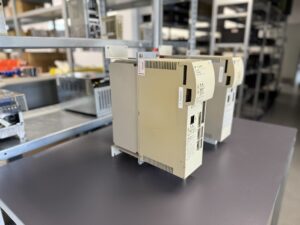
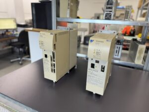
A customer sent us two interlinked units: the Inverter CIMR-M5A27P50 and the Converter CIMR-MR5N27P5.
The reported issue: sporadic alarms AL-10 (Inverter detecting Converter fault) and AL-12 (Converter undervoltage). These alarms appeared completely randomly regardless of working shifts, ambient temperature, humidity, or vibrations.
Initial testing: Both devices ran without showing any error. This is common in sporadic cases where the fault cannot be reproduced.
Our approach was a preventive overhaul:
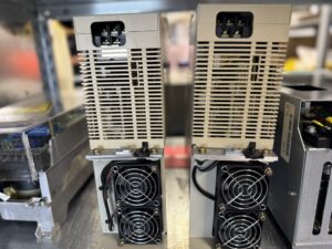
- Cleaning of heatsinks, boards, and connectors from dust, oil, and coolant residues.
- Preventive replacement of critical parts such as capacitors, relays, power transistors, and optocouplers.
- Visual inspection & solder rework where micro-cracks were found.
Test phase:
- Operation over several days on our in-house test bench.
- Stress testing with varying load cycles, speed profiles, and thermal cycles (heating and cooling).
- Documented test protocols and checklists ensured full traceability.
Result: After the overhaul, both units ran stable and error-free. The customer was able to resume production without further unexpected machine downtime.
Preventive Measures for the Customer
- Regular cleaning of the drive units and fans.
- Fan replacement every 3–5 years depending on environment.
- Insulation testing of motor cables to detect early faults.
- Checking seals and connectors to avoid moisture ingress.
- Thermal monitoring since dust and oil buildup often lead to overheating.
Conclusion
The Inverter and Converter combination is the backbone of many CNC applications. Sporadic faults are among the most difficult to diagnose and often require a preventive general overhaul. By renewing critical components and running long-term tests, the service life can be significantly extended.
For customers this means: greater reliability, fewer downtimes, and long-term protection of their investment.
Further information such as price and delivery time for:
Yaskawa Inverter CIMR-M5A27P50
Yaskawa Converter CIMR-MR5N27P5
More details about our Yaskawa repair expertise can be found here: Yaskawa Reparatur bei Industrypart
📞 Please feel free to contact us if you have any questions regarding your Omron drive technology. Our experienced team is always available to assist you.
Device Data
| Parameter | Inverter CIMR-M5A27P50 | Converter CIMR-MR5N27P5 |
|---|
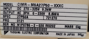
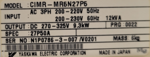
| Input | DC 270–325 V, 9.3 kW | AC 3-ph 200–220 V 50 Hz / 200–230 V 60 Hz, 12 kVA |
| Output | AC 3-ph, 0–230 V, 8.8 kVA | DC 270–325 V, 9.3 kW |
| Frequency | – | 50/60 Hz |
| Specification | 27P50A | 27P50A |
| Mass | 6 kg | 6 kg |
| Serial Number (example) | N1P0786-2-020/V0202 | N1P0786-3-007/V0201 |
| Manufacturer | Yaskawa Electric Corporation | Yaskawa Electric Corporation |
Application Environment & Compatible Equipment
This combination of converter and inverter is typically used in CNC machine tools.
- The converter supplies a stable DC intermediate circuit voltage.
- The inverter converts this DC voltage into precisely controlled AC signals for spindle and axis motors.
Applications include:
- Metalworking machine tools
- Plastic and woodworking machines
- High-performance drives in the 200-V power class
Functional Description
- Converter (CIMR-MR5N27P5): Converts incoming AC power into a stable DC bus voltage (270–325 V DC).
- Inverter (CIMR-M5A27P50): Uses PWM (Pulse Width Modulation) to generate accurate 3-phase AC output from the DC bus.
Both units are designed to work in tandem. Their interaction ensures precise torque and speed control of CNC motors.
Alarm Messages and Troubleshooting
Inverter (Selection)
| Alarm No. | Error | Cause | Solution |
|---|
| AL-01 | Overcurrent | Short-circuit or overload | Check wiring, inspect motor |
| AL-02 | Ground fault | Insulation failure motor/cables | Check insulation, repair cabling |
| AL-04 | Main fuse blown | Transistor or short-circuit fault | Replace fuse, check circuit |
| AL-05 | Output overload | Load exceeded 120% for >1 min | Reduce load |
| AL-07 | Motor locked | Mechanical jam/blockage | Check mechanics |
| AL-10 | Converter fault | Error reported from Converter | Inspect Converter |
| AL-11 | Overvoltage | Excessive DC bus voltage | Verify input supply |
| AL-12 | Undervoltage | DC bus too low | Check input voltage |
| AL-30 | Encoder error | Cable fault | Check encoder wiring |
| AL-40 | Motor overheat | Excessive motor temp | Verify cooling |
Converter
| Alarm No. | Error | Cause | Solution |
|---|
| 01 | Overcurrent | Short-circuit or overload | Check wiring and supply |
| 04 | Main fuse blown | Transistor failure, short | Inspect components |
| 05 | Overload | Load exceeded threshold | Reduce load |
| 11 | Overvoltage | Voltage > 400 V (200V class) | Verify input supply |
| 12 | Undervoltage | Voltage below threshold | Check supply |
| 14 | Servo power fault | Control supply unstable | Check servo control power |
| 15 | Frequency error | Deviation > ±5% | Verify mains quality |
| 16 | Initial charging fault | Capacitor not charged | Replace unit |
| 23 | Contactor fault | Built-in MC malfunction | Replace unit |
| 43/44 | Heatsink overheat | Insufficient cooling | Improve environment |
Components
| Type | Description | Model Reference |
|---|
| Control Board | 1PCB | YPHT31147 |
| Base Drive Board | 2PCB | YPCT21138-1B |
| Communication Board | 3PCB | YPHT31150-xC |
| Power Module | – | Power Module 7.5K |