19.10.2026 by Viktor Siebert
Yaskawa CIMR-M5S2015: power-stage damage after a loud bang
A loud bang and severe damage to the power stage
The Yaskawa VS-626M5 CIMR-M5S2015 inverter, specification 20155E, arrived at industrypart with a clear fault description: the unit had failed with a loud bang. Our inspection found a defective power stage. Several components in the drive circuitry were short-circuited or burnt. A transistor module had also been destroyed and, according to the workshop findings, had exploded.
Why the power module and its drive circuitry must be considered together
The power stage transfers energy to the motor. Its power semiconductors switch current, while the drive circuitry supplies the required control signals. These two areas work closely together. A visibly destroyed module is therefore a definite finding, but does not automatically define the complete repair scope. In this case, several drive-circuit components were also affected. Replacing only the most visibly damaged part would not have addressed these confirmed additional faults.
What the bang tells us, and what it does not
This type of failure calls for taking the unit out of service and having it professionally examined. The noise alone does not identify a particular alarm number or establish the sequence of damage. A power component may have failed first, a drive-circuit fault may have occurred, or an external stress may have contributed. The confirmed findings for this job are the damaged power stage, short-circuited or burnt drive-circuit components and the destroyed transistor module. The original initiating cause has not been documented.
The VS-626M5 in the drive system
The VS-626M5 series belongs to Yaskawa’s machine-tool spindle drives. According to its nameplate, this unit is supplied from a DC link and produces a three-phase AC output for the connected motor. For diagnosis, it helps to distinguish the supply, inverter, motor and control circuitry: a fault in one area can affect the others. The specific customer machine and connected motor model have not been identified for this repair report.
Extensive repair and preventive overhaul
We carried out extensive repairs and a preventive overhaul of the damaged power stage. The affected drive-circuit areas were addressed during the repair, and the transistor modules were replaced. We also replaced the fans and cleaned the unit. The job therefore combined repair of the actual electronic damage with work on cooling and the general condition of the unit. Individual transistor-module part numbers and quantities are not available for this documentation.
Cooling is part of assessing power electronics
Power semiconductors generate heat during operation. Heatsinks, airflow paths and fans must remove it. Contamination or deteriorating fans can increase thermal stress. This does not mean a fan caused the original failure in this case. However, the confirmed fan replacement and cleaning are important parts of the overhaul. Subsequent maintenance should also cover the surrounding cabinet so that the refurbished unit is not returned to service with heavily contaminated airflow paths.
Documentation at the test bench
An approximately 33-second test recording is available for this job. It shows the unit in the workshop and the test setup with Yaskawa drive equipment and controls. The footage complements the photographs and illustrates the test environment. It is not a complete measurement record: it does not establish the total test duration, rated load, measured temperature or approval after reinstallation. No such values are therefore claimed in this report.
Points to consider before reinstallation
Before reinstallation, the responsible qualified personnel should also assess the machine environment. This includes the motor and power cables, supply, connectors and cooling. These are inspection recommendations, not additional faults found in this job. A similar housing alone does not establish replacement compatibility. Model, complete specification, program version and machine configuration must match. The nameplate on this unit states SPEC 20155E and PRG 7038/3341.
Lessons from this repair
The Yaskawa CIMR-M5S2015 illustrates why diagnosis after severe power-stage damage must extend beyond the visibly destroyed power module. Several drive-circuit components were damaged as well. industrypart repaired and preventively overhauled the power stage, replaced transistor modules and fans, and cleaned the unit. The documented repair scope forms the basis of this report, supplemented by photographs and test footage. A complete unit designation, a legible nameplate and a precise description of the failure are useful when requesting an assessment.
Price, Lead Time and Further Information
For current repair information and an individual price and lead-time assessment, visit the Yaskawa CIMR-M5S2015 product page. Include SPEC 20155E and the complete fault description in your enquiry.
Further information: Yaskawa drive repair services. The industrypart team can assist with technical assessment, repair and testing.
Technical specifications
| Item | Value |
|---|
| Manufacturer | Yaskawa |
| Series / model | VS-626M5 / CIMR-M5S2015 |
| SPEC | 20155E |
| PRG | 7038/3341 |
| Input | DC 270–325 V; 22,9 kW |
| Output | AC 3PH; 0–230 V; 21,8 kVA |
| Mass | 12 kg |
| Origin | Japan |
Values are taken from this unit’s supplied nameplate. The kVA figure is apparent output power, not a verified motor shaft-power rating. No manufacturing date is inferred from other printed codes.
Application and compatibility
A spindle-drive application is typical for this series. The customer machine, motor, communication option and parameter set are not identified here. Verify the complete configuration before selecting a replacement; the product-page model designation alone is insufficient.
Function and assemblies
The DC link supplies the power stage. The drive circuitry controls its switching, and the output feeds the motor. Feedback and commands close the control chain. Cooling removes losses. The table separates confirmed work from general functions; component identifiers and quantities are not available.
| Assembly | Function | Confirmed work |
|---|
| Power stage | Motor power conversion | Repaired and preventively overhauled |
| Transistor modules | Power switching | Replaced |
| Drive circuitry | Switching control | Shorted/burnt components addressed in repair |
| Fans | Heat removal | Replaced |
| Unit | Assembly and housing | Cleaned |
Alarm references and troubleshooting
No numerical alarm was reported for this job. This series reference is from TOE-S626-7.2D, table 21, pages 64–65. It does not assert that any of these alarms occurred. Match the actual hardware and software documentation before applying an alarm definition.
| Code | Original designation | Meaning / check |
|---|
| AL-01 | Overcurrent | Excess current; inspect wiring. |
| AL-02 | Ground fault | Earth leakage; inspect motor insulation and cable. |
| AL-04 | Main circuit fuse blown | Fuse failure; inspect transistors and output. |
| AL-05 | Inverter output overload | Inverter overload; assess load. |
| AL-06 | Motor overload | Motor overload; reduce load. |
| AL-10 | Converter fault | Converter fault; read its display. |
| AL-11 | Main circuit overvoltage | DC-link high; inspect supply. |
| AL-12 | Main circuit undervoltage | DC-link low; inspect supply. |
| AL-43 | Heatsink overheat 1 | Heatsink hot; inspect cooling. |
| AL-48 | Internal cooling fan fault | Internal fan stopped; replace. |
Diagnosis of the main failure
The confirmed finding is physical damage to the power stage and drive circuitry. Neither a fuse change nor a reset addresses this documented damage. The initiating cause remains separate from the established repair findings. External motor, cable and supply faults should be excluded by qualified personnel before recommissioning; none is claimed as a finding in this job.
Preventive measures
Keep cooling paths clear and inspect fan condition, cabinet contamination and connectors according to operating conditions. Record intermittent faults and complete alarm displays. Electrical diagnosis belongs with qualified personnel following the manufacturer’s isolation and discharge requirements. No fixed replacement interval is specified here.
Sources
Workshop findings and supplied nameplate/photos/video; Yaskawa VS-626M5 Instruction Manual, TOE-S626-7.2D, table 21, pp. 64–65.
Repair photographs
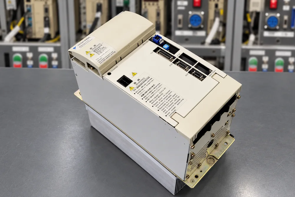 Unit after repair
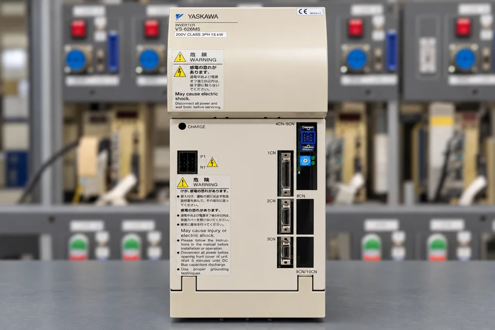 Front view after repair
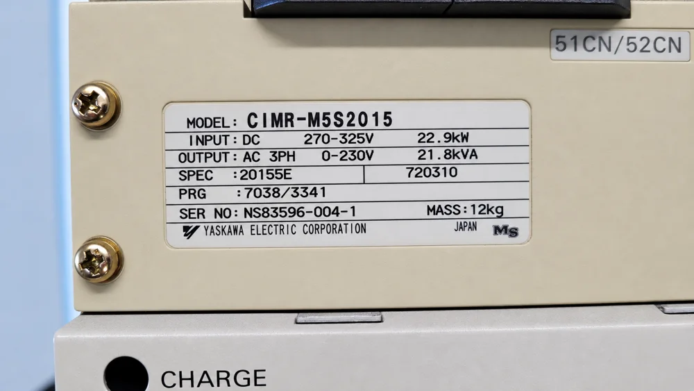 Nameplate SPEC 20155E
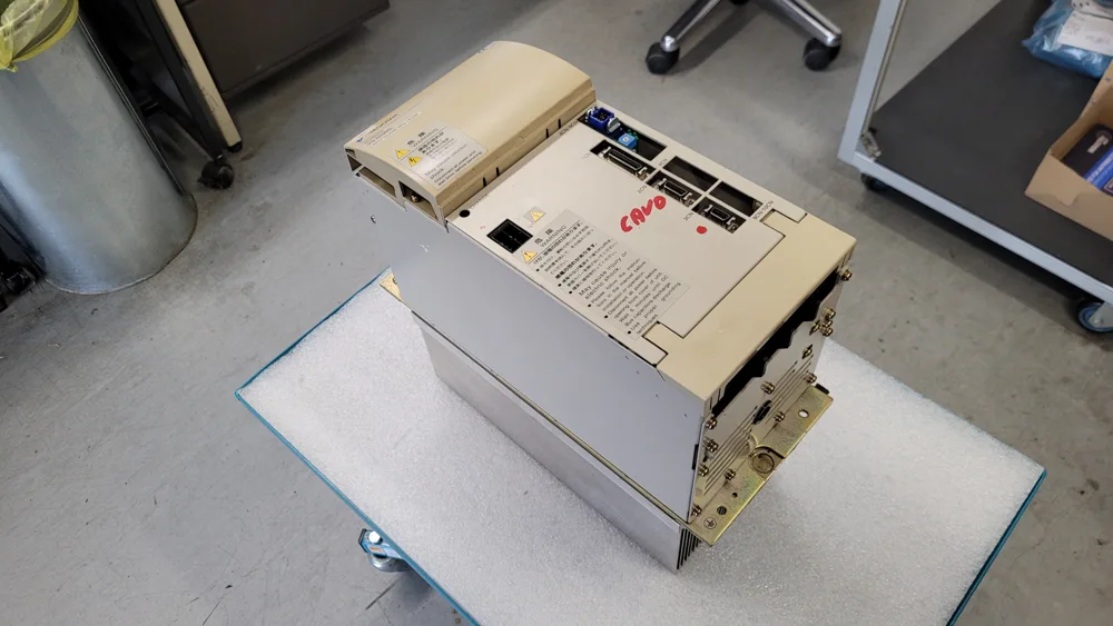 Unit before repair
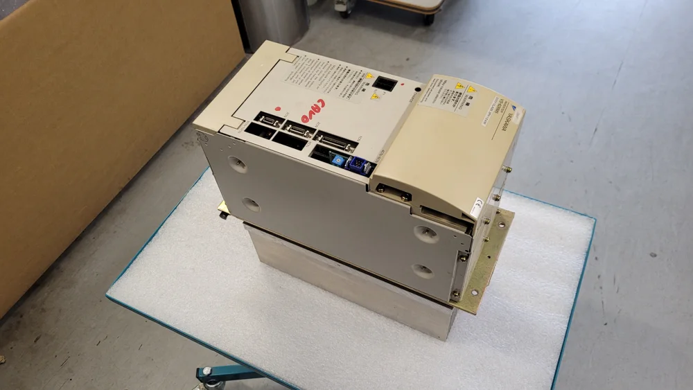 Side view before repair
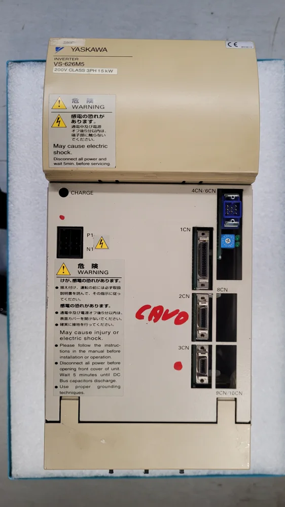 Front view before repair
Repair video