03.04.2026 by Viktor Siebert
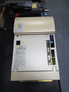
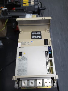
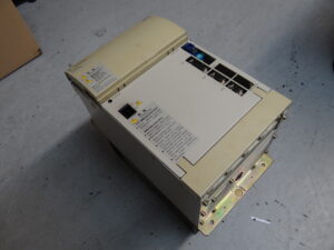
Yaskawa CIMR-M5N2030 AC Inverter Repair After Severe Spindle Motor Vibration Without Active Fault Indication
Initial situation and fault pattern
This repair case involved a Yaskawa CIMR-M5N2030 AC inverter from a machine tool application. What stood out was that in the customer’s machine everything initially pointed very strongly toward a motor fault. The spindle motor ran very loudly, noticeably rough and with massive vibration. There was no active fault message from the unit. That is exactly what makes cases like this difficult in practice. When the motor is this clearly abnormal mechanically and acoustically, the motor itself is usually suspected first.
For the customer, this kind of situation is often unsatisfactory because the cause cannot be clearly assigned while the unit is still installed in the machine. Motor, power section and machine influence each other. In this case, our recommendation was to replace the inverter first because this could be checked faster and more reliably than a complete motor removal. The customer then obtained a replacement unit. After replacing the inverter, the fault pattern in the machine disappeared immediately. That made it clear that the root cause was not primarily in the motor, even though the running behavior strongly suggested that it was.
Incoming inspection and first diagnosis
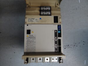
After arrival at our workshop, the inverter was tested immediately on the test bench. The technician was able to reproduce the reported behavior directly. The connected motor also ran extremely unevenly here, with clearly audible vibration excitation and noticeable running noise. This was an important point because it ruled out the machine assembly as the only cause.
During the incoming inspection, the basic function was checked first. Since there was no active fault message, the focus was on the output behavior. When measuring the output values at U, V and W, it became apparent that the phases were no longer operating evenly under load. The current distribution in particular was unequal. It is exactly these asymmetrical output conditions that cause a motor to start and rotate, but to be supplied electromagnetically in an unstable way. For the operator, this then looks like a mechanical motor fault, although the actual cause lies in the power section.
Technical analysis
The fault pattern matches a damage pattern that we already know from this series. The output stage had not completely failed yet, but it was no longer operating symmetrically. In this condition, a protective shutdown does not necessarily occur. The unit can therefore still appear to be operational, while the power delivery is already significantly distorted. That is exactly what makes this so deceptive in practice.
From a technical point of view, a weakened power stage means that the motor phases are no longer driven evenly. The motor no longer receives a clean rotating field. The result is rough running, increased noise level, clear vibration and potentially thermally unfavorable loading of the motor. From the outside, almost everything points toward a bearing problem, mechanical contact or winding fault. In reality, however, the cause may lie in aged or pre-damaged functional groups in the power drive circuitry.
In this case, several components in the power drive channels were already worn and in a critical condition. They still worked just enough that no clear alarm shutdown was triggered, but they were no longer stable enough for clean symmetrical phase control. This also explains why the motor was still rotating, but was already clearly abnormal acoustically and dynamically.
Repair measures and overhaul
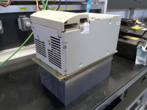
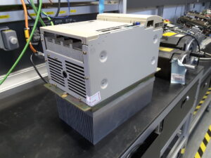
For the repair, the unit was fully opened and the affected power stages were technically reworked. The repair was not limited to a selective patch on individual parts. Instead, the critical areas of the power drive section were consistently overhauled. All functionally suspicious and typically stressed components in these stages were replaced.
In addition, the unit was cleaned, thermally relevant contact surfaces were checked and the assemblies were inspected overall for consequential damage. Since the system is operated together with an original Yaskawa CIMR-MR5N2030 AC converter, this converter was also reworked as a preventive measure. That was reasonable because in drive systems like this, inverter and converter work closely together electrically, and age-related weaknesses often do not appear in only one assembly.
The preventive part of the overhaul is important in cases like this. Once a unit has already become noticeable through asymmetrical power delivery, it is not enough to remove only the immediately visible fault. The decisive point is to return the stressed functional groups as a whole to a stable condition. That is the only way to avoid a follow-up fault shortly after the unit is reinstalled in the machine.
Final functional test
After the repair, the inverter was tested under load on the test bench. The test included power on and off behavior, smooth ramp-up, low speed, medium speed and higher speed ranges. At the same time, output behavior, phase symmetry, current balance and thermal behavior were monitored.
The most important point was that the motor, which had previously vibrated heavily, ran smoothly and evenly again after the overhaul. In this case, that direct comparison was more meaningful than any simple function release. After the repair, the running pattern was stable again, the phase currents no longer showed any abnormal imbalance and the behavior remained stable even under load changes. In addition, it was checked that no unusual temperature rise occurred in the reworked power areas.
Conclusion
This case shows very clearly that a strongly vibrating and noisy spindle motor does not automatically mean a motor defect. If an inverter operates asymmetrically in the power stage, the fault pattern can look deceptively like a mechanical failure. Especially without an active alarm message, the assignment in the machine is difficult. The sustainable solution here was the complete overhaul of the affected power stages and the additional preventive repair of the associated converter. After that, the drive ran smoothly, evenly and stably under load again on the test bench.
Before opening the unit or disconnecting plugs, always switch off the power, secure it against reconnection, wait for the discharge time and verify absence of voltage. Measurements on live parts may only be carried out by qualified electricians with suitable equipment and in accordance with local rules.
More details about our Yaskawa repair expertise can be found here: Yaskawa Reparatur bei Industrypart
📞 Please feel free to contact us if you have any questions regarding your Omron drive technology. Our experienced team is always available to assist you.
Technical Specifications
| Field | Value |
|---|
| Manufacturer | Yaskawa Electric Corporation |
| Device type | AC inverter for machine tool drive |
| Model designation | CIMR-M5N2030 |
| Series | VARISPEED 626M5 / 656MR5 |
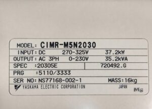
| Power | Input approx. 37.2 kW according to the nameplate photo |
| Input voltage | DC 270 to 325 V according to the nameplate photo |
| Output voltage | AC 3-phase 0 to 230 V according to the nameplate photo |
| Rated current | approx. 88 A derived from 35.2 kVA at 230 V 3-phase |
| Control type | Transistorized PWM vector control / spindle drive concept |
| Feedback | Depending on machine configuration encoder or orientation or spindle feedback, AL codes for encoder and orientation circuits are documented |
| Cooling | Forced cooling / internal cooling, fan monitoring documented |
| Protection class | approx. control cabinet unit, typically IP20 |
| Ambient temperature | approx. 0 to 55 °C for the drive system, depending on the assembly |
| Mounting | Control cabinet, vertical |
| Origin | Japan |
| Product status | Older installed series, still frequently in operation in the field |
Operating environment and possible applications
Typical machines
Machine tools, machining centers, lathes, grinding machines and spindle applications with regulated main drive. The manual data describes the system as a vector-controlled machine tool drive with regenerative structure and associated inverter and converter concept.
Typical years of manufacture
Approx. 1990s to early 2000s, depending on the machine manufacturer and retrofit status.
Typical applications
Spindle drives with speed control, orientation functions, encoder connection and CNC integration. The documented inverter alarms include encoder, orientation card, magnetic sensor and YENET communication faults, which confirms the typical integration in machine tools.
Requirements for environment and control cabinet
Clean cooling air, stable supply, short and professionally routed power and feedback lines, good grounding and sufficient thermal reserves. The manual lists among other things overtemperature, undervoltage, fan and thermistor faults as protection functions.
Notes on thermal and electrical load
Particularly critical are high load changes, repeated acceleration and braking cycles, increased control cabinet temperatures and aged cooling or power components. The fact that the system reacts to overcurrent, overload, overtemperature, undervoltage and control faults is documented in the alarm tables.
Functional description
Basic function
The CIMR-M5N2030 generates a regulated three-phase AC output for the spindle motor from a DC bus voltage. The associated system is designed as a vector-controlled machine tool drive with protection and monitoring functions.
Interaction of power section, control and feedback
The power section generates the motor phases U, V and W. The control processes setpoints, states and feedback signals. Depending on the machine configuration, encoder, orientation card or magnetic sensor may be used. The alarm table includes encoder cable faults, overspeed, speed deviation, phase C faults and position feedback faults.
Enable
Operation takes place through enable logic and status monitoring. Even though the concrete M5 manual is focused on the alarm section here, enable, alarm, ready, current limit and speed monitoring are documented as typical signal paths within the Yaskawa environment.
Protection logic
The system monitors overcurrent, overload, over and undervoltage, heatsink temperature, PCB temperature, fan function, thermistors and control faults. Converter and inverter faults are described in separate tables.
Thermal monitoring
Heatsink overheat 1 and 2, Heatsink Thermistor Disconnection, Motor overheat 1 and 2 and Control PCB Temperature Fault 1 and 2 are documented.
Signal monitoring
Among the monitored items are encoder lines, speed, speed deviation, orientation signals, YENET communication and internal A/D and EEPROM/ROM functions.
Why these functions are safety relevant
Because a drive can already have unstable phase conditions, torque fluctuations or unstable feedback even without an immediate shutdown. Exactly these conditions can lead to strong running noise, vibration, additional thermal loading and secondary faults in the machine and motor.
Alarm messages and troubleshooting
| Alarmcode | Description | Possible cause | Recommended action |
|---|
| AL-01 | Overcurrent | Output short circuit, overcurrent, wiring fault | Check wiring, check output for short circuit or ground fault |
| AL-02 | Ground fault | Ground fault on motor or output side | Check motor insulation and wiring between inverter and motor |
| AL-04 | Main circuit fuse blown | Fault in power section, load or ground short | Check load side and output wiring, repair unit |
| AL-05 | Inverter output overload | Overload at inverter output | Reduce load, check sizing |
| AL-10 | Converter fault | Fault in converter section | Check converter LED and converter faults |
| AL-12 | Main circuit undervoltage | DC bus voltage too low during operation | Check input voltage |
| AL-13 | Control circuit undervoltage | Control voltage too low | Check control supply |
| AL-30 | Encoder signal cable disconnection | Encoder line interrupted or incorrectly connected | Check encoder signal lines |
| AL-31 | Motor overspeed | Speed above 120 percent of rated setpoint | Check encoder wiring and control constants |
| AL-32 | Excessive speed deviation | Actual speed drops below 50 percent of setpoint | Check load, limit inputs, torque limits and control constants |
| AL-43 | Heatsink overheat 1 | Heatsink temperature too high | Check ambient conditions and cooling |
| AL-44 | Heatsink overheat 2 | Overtemperature for longer than one minute | Improve cooling effectiveness |
| AL-45 | Heatsink thermistor disconnection | Thermistor fault or ambient temperature too low | Check unit or raise ambient temperature |
| AL-48 | Internal cooling fan fault | Internal fan stopped | Replace fan |
| AL-d2 | CPU built-in A/D converter error | Internal A/D fault | Check or replace control PCB |
| AL-F0 | ROM error | PROM memory fault | Check or replace control PCB |
| AL-F1 / AL-F2 | EEPROM error | EEPROM fault | Check or replace control PCB |
Assembly overview
| Assembly | Functional designation | Function | Notes for testing or repair |
|---|
| Power section | Inverter output stage | Generates the three-phase output voltage for the motor | Check phase symmetry, current balance, thermal load and load behavior |
| DC bus | DC link | Supplies the power section from the converter | Check voltage stability, charging and behavior during load changes |
| Power drive circuitry | Gate and driver stage | Controls the power semiconductors phase-accurately | Particularly critical in case of unstable motor running, check for asymmetrical control |
| Control board | Control PCB | Processes setpoints, protection functions and internal monitoring | Check specifically in case of ROM, EEPROM, A/D or CPU faults |
| Cooling assembly | Heatsink and fan | Dissipates power losses | Pay attention to airflow, fan operation and thermal contact |
| Feedback section | Encoder or orientation interface | Supplies speed and position information | Check wiring, signal quality and plug connections |
| Interface section | CNC and peripheral interface | Enables, messages and communication | Check interfaces and configuration in case of communication or parameter faults |
| Converter | CIMR-MR5N2030 | Supplies the DC bus and works together with the inverter | Always consider the complete system together when inverter faults occur |