23.12.2025 by Viktor Siebert
Repair of a Yaskawa CIMR-M5A20110-XXXB Inverter Unit and CIMR-MR5N2011 Converter Unit
Initial Situation and Fault Description.
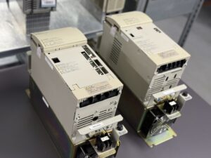
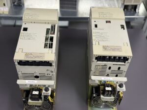
Both units, the Yaskawa CIMR-M5A20110-XXXB inverter and the Yaskawa CIMR-MR5N2011 converter, were delivered together from one machine. At the time of delivery, it was not clear to the machine operator which unit was responsible for the fault. Experience shows that converter and inverter faults often influence each other and should never be assessed separately.
On our test bench, a reproducible fault occurred under defined conditions. During braking at approximately 5300 rpm, the inverter generated alarm 11 main circuit overvoltage, while the converter simultaneously reported an output overvoltage alarm. This fault pattern is typical when braking energy can no longer be properly controlled or dissipated.
Initial Analysis and Recommendation
During the first inspection, it was already visible and measurable that several inverter components were in a critical condition. Thermal stress and aging effects were evident on power related components, which are known to cause unstable gate control behavior over time. Although the inverter was still operational at that moment, we clearly recommended overhauling both units together.
The customer decided to repair only the converter, as the inverter was still functioning in operation. This decision was documented, including a clear explanation of the potential risk of secondary damage.
Return After Two Months
Approximately two months later, both units returned to our facility. The customer reported a complaint, stating that the repaired system was showing an alarm again. However, the new inspection revealed a different fault scenario. This time, the inverter was clearly defective.
A power transistor module had completely failed. Root cause analysis showed that the failure was not initiated by the power module itself, but by a defective transistor driver stage. The driver delivered unstable control signals, which ultimately destroyed the transistor module. This risk had already been identified and communicated during the first repair.
Repair and Preventive Overhaul
During the second repair cycle, both units were fully restored. The inverter received not only a repair of the power stage but also a complete preventive overhaul of all relevant assemblies. The converter was rechecked and stabilized to ensure reliable interaction between both units.
After completion, inverter and converter were tested together under realistic load and braking conditions. The system remained stable, and no overvoltage alarms occurred even at high speeds and heavy braking cycles.
Practical Conclusion
This case clearly demonstrates the importance of treating inverter and converter systems as one functional unit. Even if a device still operates at the time of inspection, internal aging processes may already be at a critical stage. A timely preventive overhaul avoids unexpected downtime and prevents costly damage to power components.
Further information such as price and delivery time for:
Yaskawa CIMR-M5A20110-XXXB Inverter Unit
Yaskawa CIMR-MR5N2011 Converter Unit
More details about our Yaskawa repair expertise can be found here: Yaskawa Reparatur bei Industrypart
📞 Please feel free to contact us if you have any questions regarding your Omron drive technology. Our experienced team is always available to assist you.
Technical Specifications
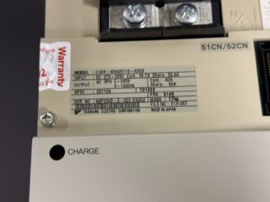
Yaskawa CIMR-M5A20110-XXXB Inverter Unit
| Parameter | Specification |
|---|
| Device type | Inverter Unit |
| Series | Varispeed 626M5 |
| Manufacturer | Yaskawa Electric Corporation |
| Supply voltage | DC 270–325 V |
| Output voltage | AC 3-phase |
| Rated output current | 25.8 A |
| Peak output current | approx. 39.3 A |
| Speed range | up to 5300 rpm |
| Control method | Vector control |
| Cooling method | Forced air cooling |
| Display | 7-segment LED |
| Communication | CNC internal interface |
| Installation | Control cabinet mounting |
| Country of origin | Japan |
Technical Specifications
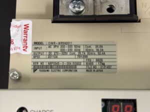
Yaskawa CIMR-MR5N2011 Converter Unit
| Parameter | Specification |
|---|
| Device type | Converter Unit |
| Series | Varispeed 656MR5 |
| Manufacturer | Yaskawa Electric Corporation |
| Input voltage | AC 3-phase 200–220 V |
| Input frequency | 50 / 60 Hz |
| Output voltage | DC link |
| Rated output current | 25.8 A |
| Regenerative function | Integrated |
| Cooling method | Forced air cooling |
| Display | 7-segment LED |
| Installation | Control cabinet mounting |
| Country of origin | Japan |
Typical Application and System Integration
The combination of the MR5 converter unit and the M5 inverter unit is typically used in CNC machine tools, especially in applications with high dynamic requirements such as frequent acceleration and deceleration cycles.
Typical applications include:
- CNC lathes
- Machining centers
- Milling machines
- Rotary axes with high regenerative energy
The converter and inverter operate as a single functional system. The converter manages power supply and regenerative energy, while the inverter controls motor current, torque and speed.
Functional Description of Converter and Inverter Interaction
The converter unit generates a stabilized DC link voltage from the three-phase AC supply. During deceleration, kinetic energy from the motor is fed back into the DC link. This energy must be processed and controlled by the converter.
The inverter unit converts the DC link voltage into a precisely controlled three-phase AC output for the motor. It continuously monitors current, voltage and temperature to ensure safe operation.
If the regenerative energy cannot be properly absorbed or controlled, the DC link voltage rises. This condition leads to overvoltage alarms on both the inverter and the converter.
Inverter Alarm List
CIMR-M5 Series (Excerpt)
| Code | Alarm description | Possible cause | Corrective action |
|---|
| AL-01 | Overcurrent | Short circuit or overload | Check wiring and load |
| AL-04 | Main circuit fuse blown | Power stage fault | Inspect power module |
| AL-05 | Output overload | Continuous overload | Reduce load |
| AL-06 | Motor overload | Excessive thermal load | Check mechanical system |
| AL-10 | Converter fault | Converter error detected | Inspect converter |
| AL-11 | Main circuit overvoltage | DC link overvoltage | Check regenerative behavior |
| AL-31 | Overspeed | Speed exceeds limit | Verify parameters |
| AL-40 | Heatsink overheat | Insufficient cooling | Check fan and airflow |
| AL-48 | Cooling fan fault | Fan stopped or defective | Replace fan |
Converter Alarm List
CIMR-MR5 Series (Excerpt)
| Code | Alarm description | Possible cause | Corrective action |
|---|
| 01 | Overcurrent | Excessive current | Check wiring and load |
| 04 | Main circuit fuse blown | Power stage damage | Inspect converter |
| 05 | Overload | Continuous overload | Reduce load |
| 11 | Output overvoltage | Excessive regenerative energy | Check braking conditions |
| 12 | Undervoltage | Low input voltage | Check power supply |
| 15 | Frequency fault | Supply frequency deviation | Check power source |
| 16 | Initial charging fault | DC link charging failure | Replace unit |
| 43 | Heatsink overheat | Cooling insufficient | Improve ventilation |
| 45 | Thermistor fault | Temperature sensor failure | Replace unit |
Main Components
CIMR-M5A20110-XXXB Inverter Unit
| Assembly | Designation | Function |
|---|
| Control board | Control PCB | Control logic and monitoring |
| Drive board | Base drive PCB | Gate signal generation |
| Communication board | Interface PCB | CNC communication |
| Power module | Transistor module | Power conversion |
| Cooling system | Fan assembly | Heat dissipation |
Main Components
CIMR-MR5N2011 Converter Unit
| Assembly | Designation | Function |
|---|
| Control board | Control PCB | Voltage regulation |
| Power board | Rectifier PCB | AC to DC conversion |
| Power stage | Power module | Energy processing |
| Cooling system | Fan assembly | Heat dissipation |
Preventive Maintenance Recommendations
- Always evaluate inverter and converter as a combined system
- Investigate overvoltage alarms during braking immediately
- Ensure proper cooling and clean airflow paths
- Perform preventive refurbishment before power stage damage occurs
- Verify braking and deceleration parameters regularly