04.10.2026 by Viktor Siebert
Yaskawa CACR-SR44BE12G-E: Power supply failure and Alarm 10 at RUN
Yaskawa CACR-SR44BE12G-E repair for failure to power up and Alarm 10
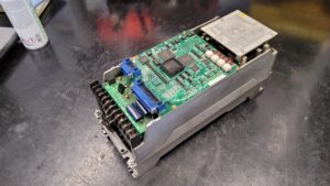
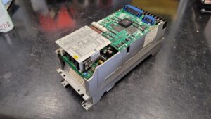
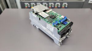
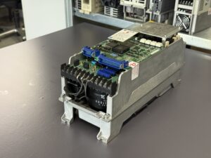
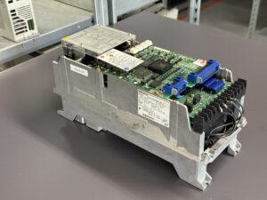
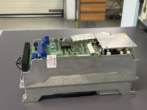
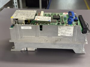
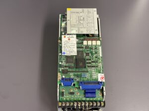
A Yaskawa Servopack CACR-SR44BE12G-E from Rome, Italy, would no longer power up. Our examination identified a fault in the internal power supply. After repair, the unit powered up again, but Alarm 10 appeared as soon as the RUN signal was applied. Further diagnosis confirmed an additional power output stage fault. We repaired both assemblies and carried out a standard overhaul.
Restoring the internal power supply came first
The internal power supply powers the electronic circuits of the Servopack. Without this auxiliary supply, the control electronics cannot operate correctly. Restoring it is necessary before the amplifier can be assessed when enabled and during motor operation.
After repairing the power supply, we continued the diagnosis. No further fault was initially apparent at power-up. Enabling the drive with RUN then showed that the power section also required investigation.
Alarm 10 appeared with the RUN signal
As soon as RUN was applied, Alarm 10 appeared. The supplied Yaskawa alarm table lists display A.10 as “Overcurrent or overheat”. The code alone therefore does not identify a single defective component. The point at which the alarm appears is also part of the diagnosis.
The table distinguishes, among other situations, faults when control power is switched on, when the main circuit is energised and during operation. Depending on the circumstances, possible causes include the control electronics, current feedback circuit, power transistor module, a motor ground fault, and fan or ambient temperature problems. These possible causes must be distinguished from the actual workshop findings.
Further examination confirmed an additional power output stage fault. Restoring the power supply made this second fault detectable. This case shows why diagnosis needs to continue after the first defect has been corrected.
What the servo amplifier does
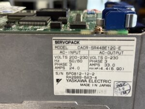
The CACR-SR44BE12G-E belongs to the Yaskawa CACR-SR-BE family. Its nameplate specifies 4.4 kW. The three-phase input is rated at 200 to 230 V, 50 or 60 Hz. The output specifications are 0 to 230 V, three phases and 33.0 A. The input current stated on the nameplate is 24.0 A. These two current ratings refer to different sides of the unit.
A servo amplifier converts commands from the machine controller into a controlled electrical supply for the associated motor. Motor feedback allows the control system to monitor its movement. The power output stage switches the motor currents, while the internal power supply provides auxiliary power for the electronic functions. A fault in either area can disable the entire drive, even though the symptoms differ considerably.
Repair and standard overhaul
We repaired the internal power supply and the defective power output stage. The Servopack also received our standard overhaul. The repair therefore addressed both confirmed faults.
The assembly list includes the CACR-SR1B control board, the CACR-F2TBI-E power board and the power section. Their technical details are summarised in the components table below.
An overhaul also considers connectors, cooling paths and adjacent circuits. The ageing components assessed or replaced depend on the condition of the unit and the agreed repair scope.
Examination on the servo test bench
A video recording of our test bench accompanies this repair case. It shows the connected Servopack, the test controls and the motors on the bench. The relevant transition here is from a powered unit to an enabled drive: the second fault had only appeared when the RUN signal was applied.
A check limited to powering up would not adequately cover this fault pattern. The response to enable signals, commands and motor movement also matters. Power supply, feedback and power electronics must work together. The embedded video shows part of the process on our servo test bench.
What operators can record when a similar fault occurs
A useful fault description distinguishes between a completely dark display and an alarm that appears only at start-up. The complete display, the moment the fault occurs and the unit’s behaviour after switching on should also be recorded. These details help distinguish a supply failure from a fault that only becomes apparent when the output stage is active.
Clean ventilation paths, unobstructed heat sinks and functioning fans support heat dissipation. Connectors and motor cables should be inspected by qualified personnel during maintenance. If an overcurrent alarm recurs immediately, its cause should be investigated before further start attempts. Work on the power section requires compliance with manufacturer instructions and consideration of energy stored in the DC link.
Two findings in one repair case
This Servopack from Rome shows why diagnosis must continue after the first fault has been corrected. Initially, the defective internal power supply prevented operation. Alarm 10 at RUN then revealed the additional power output stage fault. Both findings formed part of the unit’s repair and subsequent overhaul.
Price, Lead Time and Further Information
Information on price and lead time for the Yaskawa Servopack CACR-SR44BE12G-E is available on the corresponding CACR-SR-BE product page. This model variant is explicitly listed there. The exact service scope and availability are agreed for the specific order.
Further information about our repair services for Yaskawa CACR-SR Servopacks is available in our service section.
Please contact us with questions about your Yaskawa drive technology or a specific fault. We can assist with the technical assessment, repair and testing of your unit.
Technical Specifications
| Feature | Technical information |
| Manufacturer | Yaskawa Electric, Japan |
| Model | CACR-SR44BE12G-E |
| Alternative search spelling | CACR-SR44BE12GE |
| Unit type | AC servo amplifier, SERVOPACK |
| Series | CACR-SR..BE |
| Nameplate power | 4.4 kW (5.90 HP) |
| Input | 200–230 V AC, 3 phases, 50/60 Hz |
| Nameplate input current | 24.0 A |
| Output | 0–230 V AC, 3 phases |
| Nameplate output current | 33.0 A |
| Documentation reference | Nameplate and supplied Table 14.2, Section 14.2.1 “LED Indication (7-segment) for Troubleshooting” |
Application Environment and Compatible Equipment
The amplifier works together with a machine controller, servo motor and suitable feedback. Before replacement, compare the complete model designation including BE12G-E, hardware configuration, connections and unit-specific settings.
Functional Description
The main supply provides electrical energy for the motor. The output stage converts it into the controlled three-phase motor supply. Commands, enable signals and feedback determine operating behaviour. The internal power supply powers the electronic circuits.
Components
The following table lists the documented Servopack assemblies and their functions. It is not a list of replaced individual components.
| Assembly | Designation | Quantity | Function | Inspection or repair |
| Control board | CACR-SR1B | 1 | Control and signal processing | Check supply, enable and signals together |
| Power board | CACR-F2TBI-E | 1 | Power section circuitry | Check drive circuitry and connections to power section |
| Power section | Not specified | 1 | Switching motor power | Confirmed defective and repaired in this case |
Alarms and Troubleshooting
The following overview is based on Yaskawa alarm Table 14.2. Possible causes and actions depend on when the alarm occurs. The manufacturer’s instruction “Replace the SERVOPACK” refers to replacing the unit; industrypart performed the assembly-level repair described in this case.
| Code | Original name | Meaning | Possible cause | Action in table |
| A.10 | Overcurrent or overheat | Overcurrent or overheating | Output stage, current feedback, motor ground fault, fan or temperature; state-dependent | Check grounding and fan; replace for internal faults. Do not switch on again with a defective transistor module. |
| A.20 | Circuit protector tripped | Circuit protector tripped | Control board, thyristor module or MCCB state | Identify MCCB state; replace or switch MCCB on as specified for the condition. |
| A.30 | Regenerative fault | Regenerative circuit fault | Control board, regenerative transistor or resistor connection | Check resistor connection; replace SERVOPACK as appropriate. |
| A.40 | Overvoltage | Overvoltage | Excessive load inertia or defective regenerative circuit | Check load inertia; replace for internal circuit fault. |
| A.51 | Overspeed | Overspeed | Motor/encoder connections or gain settings | Check wiring, encoder phases A/B/C and gains. |
| A.60 | Undervoltage | Undervoltage | Defective main circuit thyristor-diode module | Replace SERVOPACK according to table. |
| A.71 | Instantaneous overload | Instantaneous overload | Operation above rated torque | Check overload and adjust as necessary. |
| A.72 | Continuous overload | Continuous overload | Control board or incorrect motor wiring | Replace for board fault; correct motor wiring. |
| A.C1 | Overrun detection | Overrun detection | Motor or encoder connection | Correct motor or optical encoder connection. |
| A.C2 | Phase detection error | Phase detection error | Incorrect encoder connection | Correct optical encoder signal wiring. |
| A.C3 | Phase PA/PB disconnection | Encoder phase PA/PB disconnection | Disconnected A/B encoder signals | Correct encoder signal wiring. |
| A.C4 | Phase PC disconnection | Encoder phase PC disconnection | Disconnected C encoder signal | Correct encoder signal wiring. |
| A.F1 | Open phase of power supply | Open supply phase | Missing supply phase | Check main circuit power supply. |
| A.F2 | Power supply rise error | Power supply rise error | Large power supply distortion | Check main circuit power supply. |
| A.04 | Parameter setting error | Parameter setting error | Value outside setting range | Set parameter correctly. |
Diagnostic Notes on the Main Fault
Alarm 10 is listed as A.10 in the table and means overcurrent or overheating. In this Servopack, it appeared with the RUN signal after the internal power supply had been repaired. Further examination confirmed the additional power output stage fault.
The moment the alarm appears helps narrow down the investigation but does not replace technical testing. Depending on operating conditions, other possible causes include current feedback, control electronics, a motor ground fault or cooling problems. Avoid further power-up attempts if an output stage fault is suspected; the manufacturer’s table explicitly warns against switching on again with a defective main circuit transistor module.
Preventive Measures
Inspect ventilation paths and heat sinks regularly according to operating hours and contamination. Have qualified personnel check fan operation. Include motor cables, protective earth and connectors in maintenance. Record recurring alarms with the complete display and operating state. During overhaul, assess auxiliary supplies and ageing components according to findings. The supplied material does not establish fixed maintenance intervals for this unit type.