14.01.2026 by Viktor Siebert
Repair of a Yaskawa CACR-5R5-PD1VDS01 Servopack with Alarm A.33 Caused by Defective Brake Electronics
Initial Situation and Fault Description.
The Yaskawa Servopack CACR-5R5-PD1VDS01 was delivered with an unusual fault description. When the mains supply was switched off via R S T, the internal status indicator did not turn off as expected. When the supply was switched on again, the unit consistently reported alarm A.33 during startup. As a result, the machine could no longer be released for operation because the servopack did not initialize correctly and the axis could not be enabled safely.
This behavior already indicated that the issue was not limited to a classic power or supply fault. Instead, it pointed to a problem in the interaction between control logic, internal power supply, and the connected brake electronics. Especially in older CACR servopacks, the brake electronics are closely linked to internal monitoring functions, so deviations in this area can easily trigger follow-up alarms.
Incoming Inspection and Initial Diagnosis
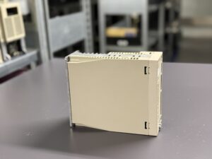
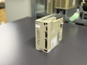
After the incoming inspection, the servopack was first visually examined. The housing and cooling areas showed no external damage, but age-related signs such as dust accumulation in the ventilation areas were visible. The next step was an electrical pre-check on the test bench.
When the mains supply was deliberately switched off via R S T, the behavior described by the customer could be reproduced clearly. The display remained active, indicating faulty discharge behavior or backfeeding within the internal power structure. After switching the supply back on, alarm A.33 appeared immediately. In the context of this servopack, this alarm is associated with a malfunction related to holding and brake functions.
This combination is typical when the brake electronics no longer operate cleanly and residual voltages or implausible signal states feed back into the control logic.
Technical Analysis of the Brake Electronics
In the next step, the servopack was opened and the internal assemblies were systematically inspected. Special attention was given to the brake control assembly, as it supplies the motor brake and controls its timed release and monitoring.
Measurements showed that the brake electronics no longer provided stable switching states. In the powered-down condition, a residual voltage remained that was not discharged within the specified time. When the unit was powered on again, the internal logic interpreted this condition as an incorrect brake release, directly triggering alarm A.33.
The root cause was aged and electrically unstable brake electronics that could no longer reliably perform their defined function. Such effects usually develop gradually and often become visible only after power interruptions or emergency stop events in machine operation.
Repair Measures and Overhaul
The defective brake electronics were completely reconditioned. The repair was not limited to restoring basic functionality but included targeted preventive refurbishment. Age-sensitive components were renewed, contact points were inspected, and the internal voltage paths were stabilized.
After the repair, the servopack was thoroughly cleaned to remove dust and deposits that can cause long-term thermal and electrical issues. The unit was then reassembled and put back into operation on the test bench.
Multiple cycles of power on, power off, and re-energizing were performed. The shutdown behavior was clean, the display switched off correctly, and the startup process was free of alarm messages. The brake electronics once again operated synchronously with the internal control logic, and alarm A.33 no longer occurred.
Final Functional Test
The final functional test included both electrical and logical checks. The servopack was operated under nominal conditions, including multiple brake cycles and simulated power interruptions. All protection and monitoring functions responded as expected.
Particular attention was paid to the timing sequence of brake release, servo enable, and voltage discharge. These sequences are critical for machine safety and were fully restored after the repair.
Conclusion
The Yaskawa CACR-5R5-PD1VDS01 showed a classic age-related failure pattern in which defective brake electronics led to a reproducible alarm A.33. Through targeted diagnosis, professional repair, and preventive overhaul, the servopack was fully restored to reliable operation. This case clearly demonstrates the importance of systematic analysis and in-depth understanding of internal interactions in older drive systems.
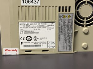
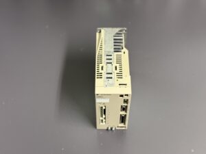
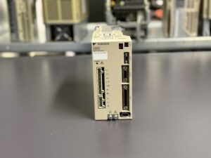
Information about the mentioned Servopack: Yaskawa Servopack CACR-5R5-PD1VDS01
Further details on our Yaskawa repairs can be found here: Yaskawa Sigma V Repair
📞 Feel free to contact us if you have any questions regarding your Yaskawa drive technology. Our team will be happy to assist you.
Technical Specifications
| Feature | Value |
|---|
| Manufacturer | Yaskawa Electric Corporation |
| Device type | AC Servopack |
| Model designation | CACR-5R5-PD1VDS01 |
| Series | CACR |
| Rated power | approx. 0.75 kW |
| Input voltage | Single-phase 200–230 V AC, 50/60 Hz |
| Input current | approx. 8.8 A |
| Output voltage | Three-phase 0–230 V / 0–400 V |
| Output current | approx. 5.5 A |
| Control type | Analog servo system |
| Feedback | Incremental encoder |
| Brake control | Integrated brake electronics |
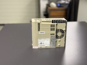
| Cooling | Air cooling, integrated fan |
| Protection class | IP10 |
| Ambient temperature (operation) | 0 to 55 °C |
| Mounting | Control cabinet, vertical |
| Origin | Japan |
| Product status | Discontinued, service and repair supported |
Application Environment and Typical Uses
The Yaskawa CACR-5R5-PD1VDS01 is typically used in older CNC and special-purpose machines where robust analog servo drive technology is required. Common applications include machine tools, machining centers, packaging machines, and custom-built systems with controlled axes.
The unit is designed for applications requiring precise speed and torque control and reliable control of a motor holding brake.
The typical environment is a control cabinet with forced ventilation. Due to the thermal design, clean cooling paths and sufficient airflow are essential.
Functional Description
The CACR-5R5-PD1VDS01 is an analog-controlled AC servo amplifier designed to drive Yaskawa servo motors with incremental feedback. It provides motor power, processes command signals from the machine control, and evaluates encoder feedback signals.
A key component of the system is the integrated brake electronics. These control the motor holding brake in a defined timing sequence relative to servo enable and monitor correct operation during power on and power off. Faults in this area can directly trigger alarms because safe axis release cannot be guaranteed.
In addition, the servopack includes internal protection functions such as overcurrent, overvoltage, undervoltage, and overtemperature monitoring. These mechanisms ensure the drive is safely shut down under critical conditions.
Alarm Messages and Troubleshooting
| Alarm code | Description | Possible cause | Recommended action |
|---|
| A.10 | Overcurrent | Motor short circuit, defective power stage | Check motor and power electronics |
| A.20 | Overvoltage | Regenerative energy, braking issue | Check braking and mains supply |
| A.30 | Undervoltage | Mains problem, unstable internal supply | Check mains and power supply |
| A.33 | Brake error | Defective or unstable brake electronics | Inspect and repair brake electronics |
| A.40 | Overtemperature | Fan failure, clogged heat sinks | Check cooling, clean unit |
| A.50 | Encoder error | Signal loss, cable issue | Check encoder and wiring |
| A.51 | Encoder communication | Loose or corroded contacts | Inspect connectors |
| A.70 | Servo enable error | Implausible enable signals | Check control logic and I O |
| A.80 | Internal control error | Aged electronics | Repair required |
| A.90 | Initialization error | Startup sequence fault | Check supply and logic |
Assembly Overview
| Assembly | Designation | Function | Inspection or repair notes |
|---|
| Power stage | Power module | Drives motor phases | Current measurement, thermal inspection |
| Control board | Control board | Regulation, logic, alarm handling | Visual inspection, voltage checks |
| Brake electronics | Brake control unit | Controls motor holding brake | Check timing behavior and residual voltages |
| Power supply section | Power supply | Supplies internal assemblies | Verify voltage stability |
| Fan unit | Cooling fan | Heat dissipation | Check operation and bearing noise |
| Encoder interface | Feedback interface | Evaluates incremental encoder | Check signal quality and connectors |
| Terminal blocks | Power and signal terminals | Connection to motor and control | Inspect screws and contacts |