12.11.2026 by Viktor Siebert
Yaskawa SGMP-08AWMN31: encoder alarm and mechanical wear
On a Yaskawa SGMP-08AWMN31, feedback faults and mechanical wear can occur together. Project 123365 was reported with alarms A.81 and A.00. Inspection revealed worn bearings, an abnormal brake condition and a feedback-system fault. This article explains how to assess these areas and which checks matter before returning the drive to service.
Application and function of the SGMP-08AWMN31
The AC servo motor converts commands from the Servopack into controlled motion. The encoder supplies feedback for the control loop, while the holding brake provides its intended holding function. Typical applications include controlled feed and positioning tasks. The specific machine and axis were not documented for this repair.
The submitted system included a Yaskawa SGDB-10ANY11 Servopack. Motor, feedback, brake, cables and controller must be assessed as a system. A similar model designation alone does not establish interchangeability.
Technical data from the original nameplate
| Item | Specification |
|---|
| Manufacturer / model | Yaskawa / SGMP-08AWMN31 |
| Type | AC servo motor |
| Rated output | 750 W |
| Rated voltage / current | 200 V / 4.1 A |
| Rated torque | 2.39 N·m |
| Rated speed | 3,000 rpm |
| Insulation class | B |
| Manufacturing date | September 1998 |
| Controller supplied for this repair | SGDB-10ANY11 |
The 750 W rating is taken from the photographed nameplate of this motor. Before working on this particular version, verify the pin assignment, brake supply and parameters against the applicable documentation.
Findings: assess electrical condition, mechanics and feedback separately
Incoming inspection recorded satisfactory resistance, high-voltage and insulation checks. However, the bearings were worn and the brake produced clearly audible signs of wear. AL.81 was recorded at the feedback system. The motor ran again on the test bench after a reset. Temporary recovery does not rule out a recurring fault.
Age-related wear was suspected. Cable faults, poor connections and interrupted backup power are general possibilities when investigating feedback faults, but were not established as the sole cause here. A Servopack alarm alone is therefore insufficient reason to replace the complete motor without further investigation.
A practical diagnostic sequence
First record the alarm, power-up condition and point at which the fault occurs. Then confirm the nameplates, system combination and cables. With the system safely isolated, inspect connections and the feedback link, followed by the mechanical and brake condition. Electrical measurements must suit the component being tested; feedback electronics must not be subjected to unsuitable test voltages.
Only reset after investigating the cause and securing the machine data. Absolute-position systems may require referencing or adjustment afterwards. Electrical drive and motion-axis work must be performed by qualified personnel, taking stored energy and unintended axis movement into account.
Overhaul and final system test
The motor was dismantled, cleaned of rust and contamination, washed and dried. The overhaul covered mechanical functions, braking and feedback. Connection areas, cable entries and the encoder compartment were sealed. Reassembly and painting were followed by adjustment and testing, including resetting the zero point.
A successful final test with the customer’s drive was recorded on 17 June 2026. This checked the interaction between the overhauled motor and its associated controller.
Prevention and sources
Record bearing noise, changes in holding behaviour and recurring encoder alarms early. Protect cables against tension and abrasion, and keep moisture and contamination away from connections. After work on the position system, complete the machine-specific adjustments and safety checks.
This case is based on the repair record and original photographs for project 123365. The general alarm reference follows the Yaskawa Σ Series SGM□/SGDB User’s Manual, TSE-S800-16E, section 6.2.1, printed page 513, and Appendix D, pages 570 to 572 (PDF pages 522 and 576 to 578). This reference covers the SGDB series. Machine-specific and version-specific documentation must also be consulted for the SGDB-10ANY11 variant.
Video: findings, overhaul and testing
Yaskawa SGMP-08AWMN31: repair process with original photographs and test footage, English.
Original photographs from the repair record
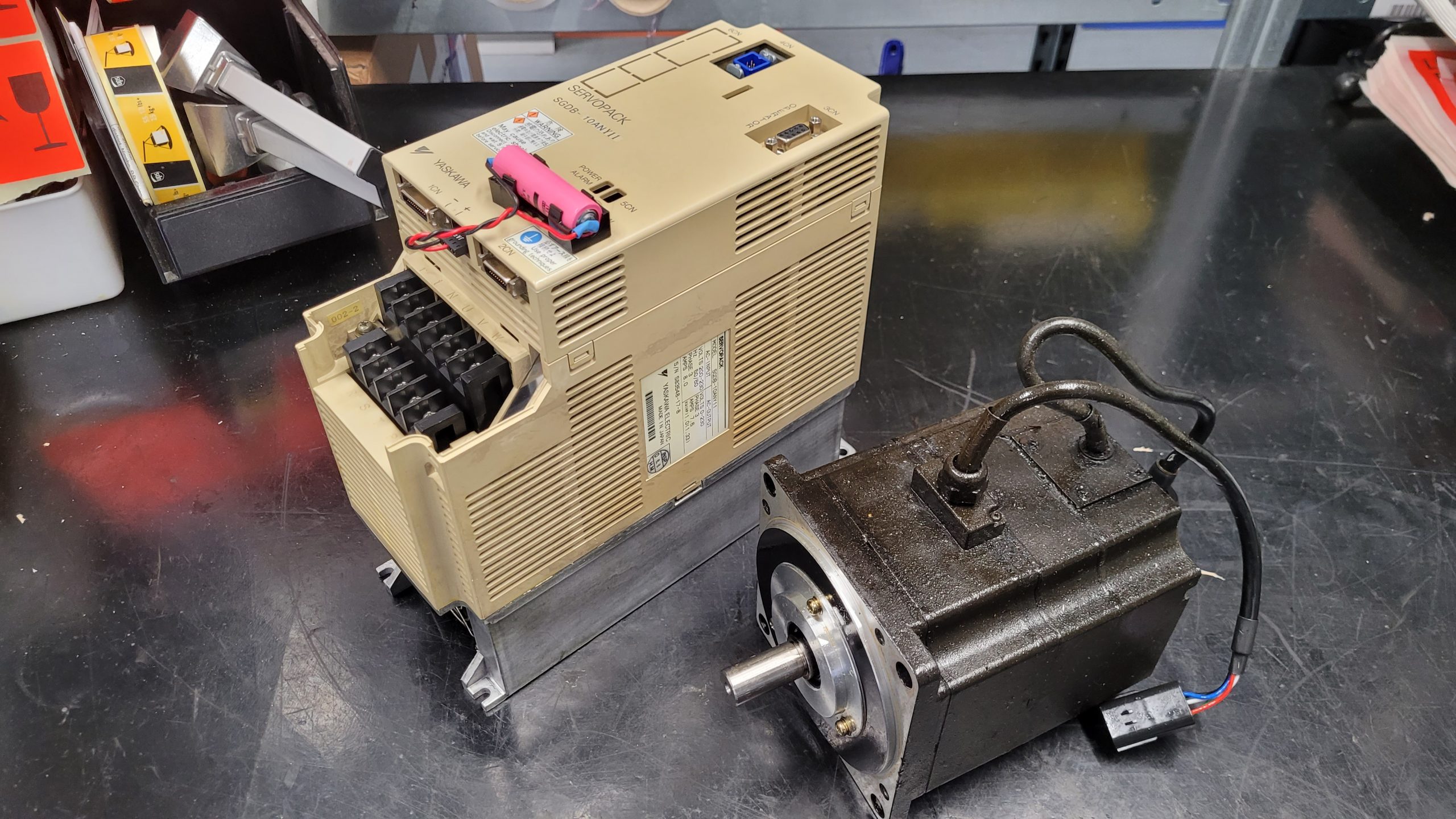 Yaskawa SGMP-08AWMN31 with SGDB-10ANY11 Servopack before repair.
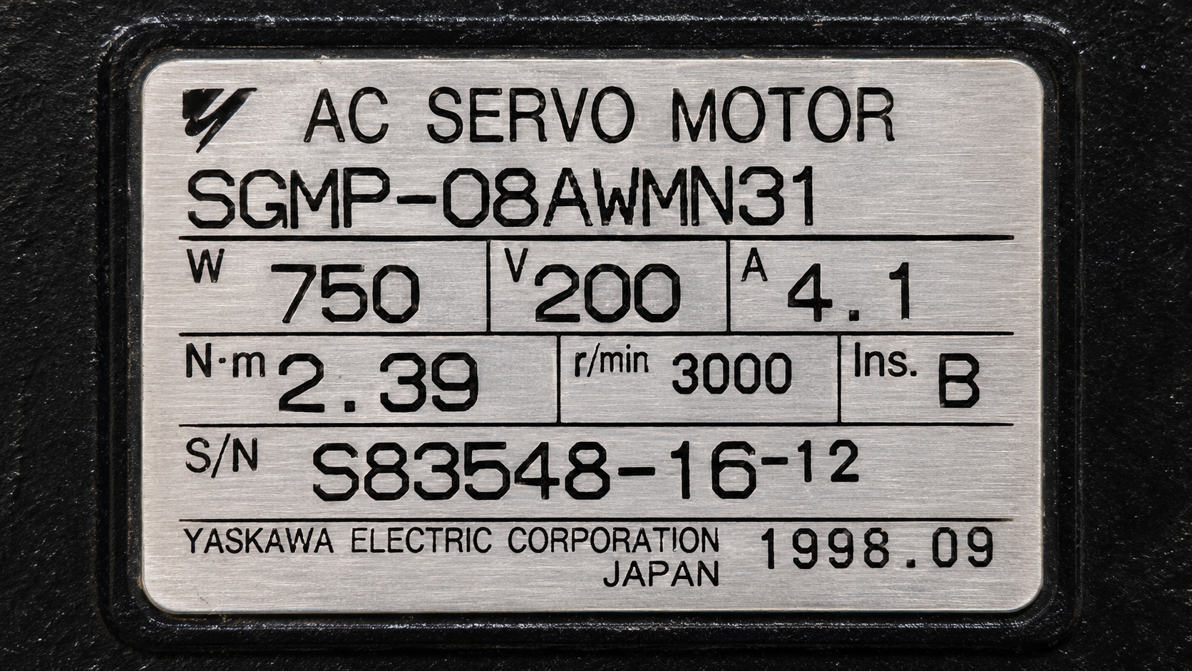 Yaskawa SGMP-08AWMN31 nameplate showing the 750 W rating.
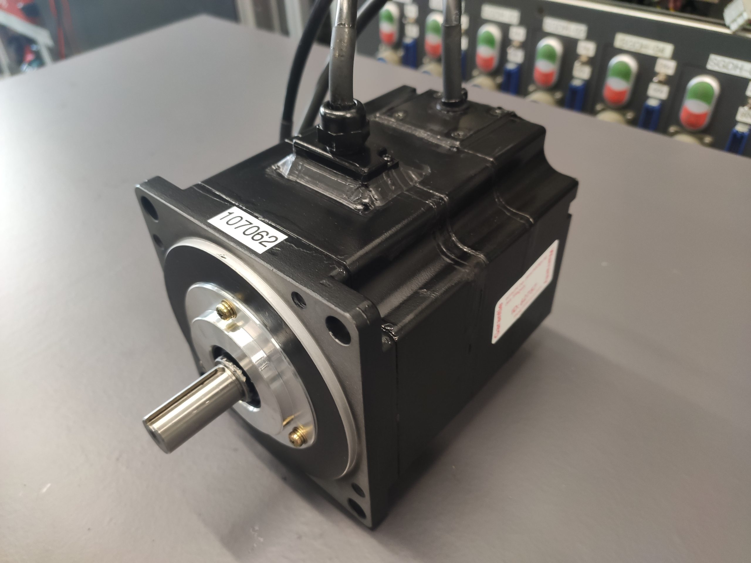 Yaskawa SGMP-08AWMN31 after repair, shaft-side view.
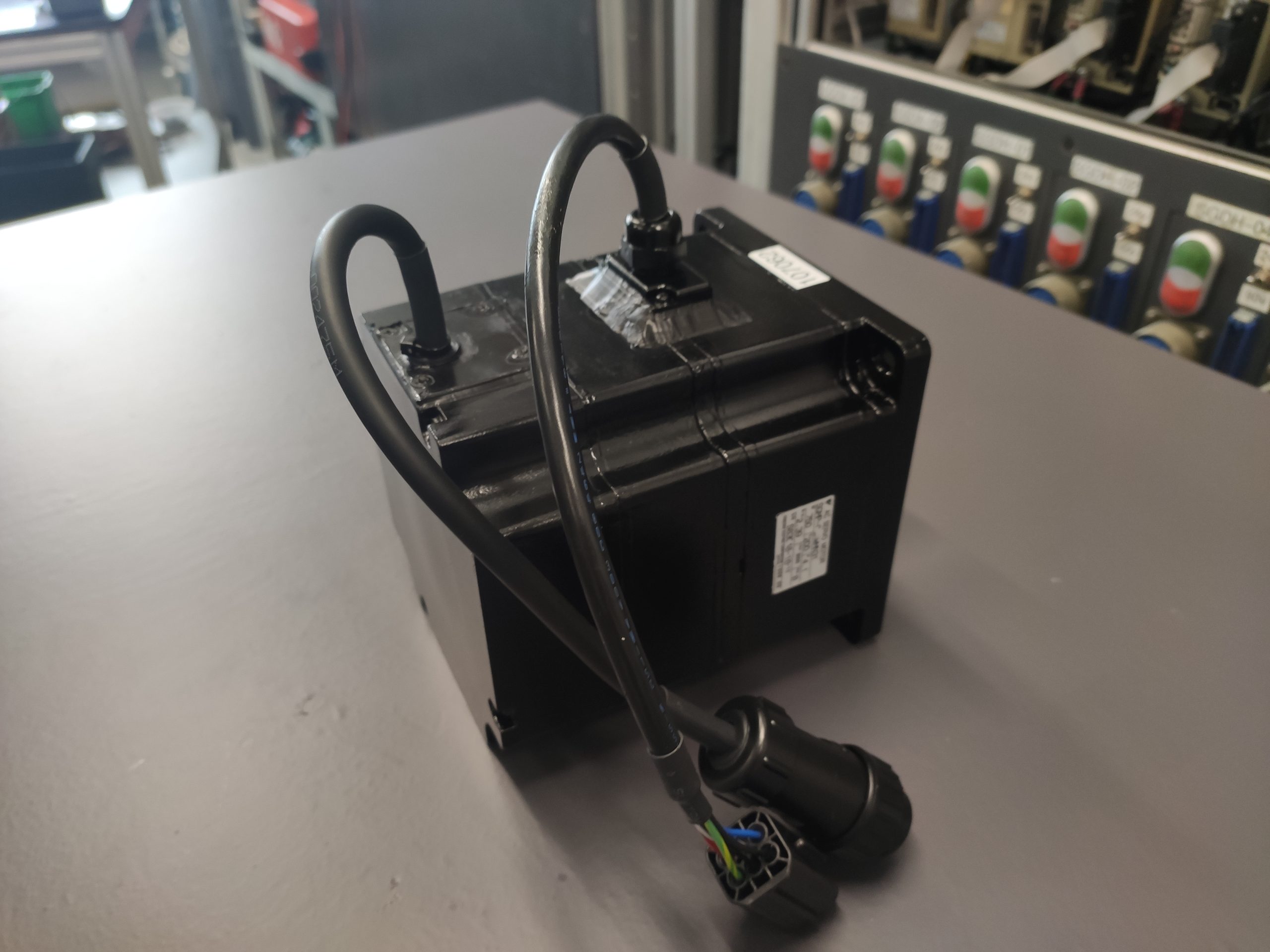 Yaskawa SGMP-08AWMN31 after repair, connection side.
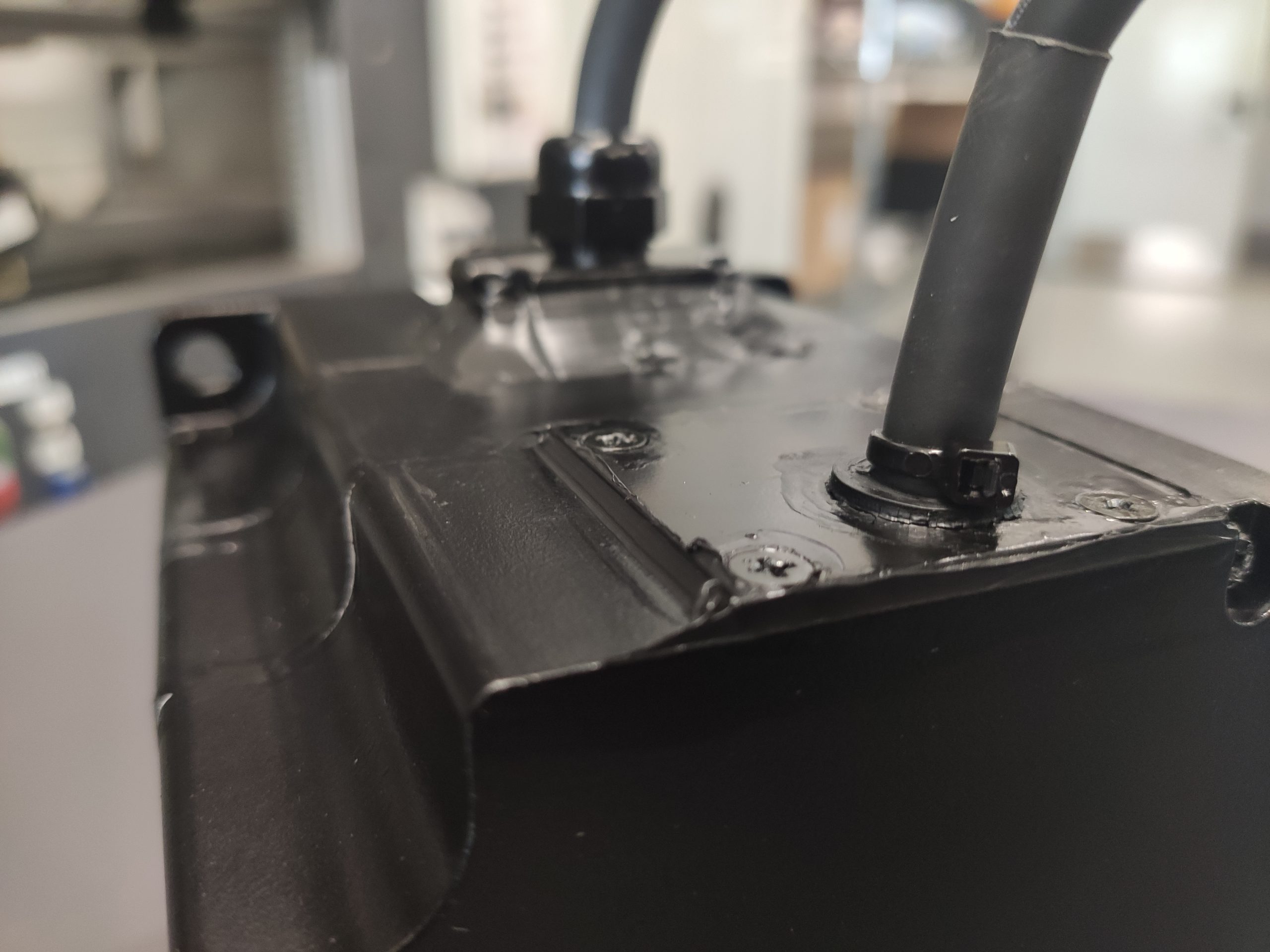 Yaskawa SGMP-08AWMN31 after repair, cable entries.
Request a repair and check current prices
Would you like your SGMP-08AWMN31 inspected or overhauled? Send us the complete model designation, a nameplate photograph, the controller model and the exact alarm. Please also indicate whether the fault occurs during power-up, enabling or movement.
https://www.industrypart.com/products/yaskawa-sgmp-08awmn31-servo-motor-19917.html
https://www.industrypart.com/manufacturers/yaskawa
SGDB Servopack alarm reference
These notes concern controller diagnostics, not internal motor codes. A.81 and A.00 were reported for this case; the other codes are general reference information. Source: TSE-S800-16E, Appendix D, printed page 570 (PDF page 576).
| Code | Meaning in brief |
|---|
| A.00 | Absolute-position information missing or invalid |
| A.02 | Parameter checksum fault |
| A.04 | Parameter outside permitted range |
| A.10 | Excess current |
| A.31 | Excessive position deviation |
| A.40 | Main-circuit voltage fault |
| A.71 | Overload at high load |
| A.72 | Overload at lower load |
| A.80 | Invalid absolute-encoder pulse count |
| A.81 | Backup power lost, 12-bit absolute encoder |
For A.81, the manual describes loss of all three power sources for the affected absolute encoder. The alarm alone does not identify a single defective component. Supply, connection and feedback must be assessed together; applicability depends on the actual encoder version.
Further troubleshooting by symptom
| Observation | Focus of investigation |
|---|
| Alarm immediately at power-up | Record fault history, position data and feedback power conditions |
| Fault disappears after a reset | Continue investigating and verify position reference before enabling |
| Unusual running noise | Inspect mechanical and bearing condition with the system secured |
| Abnormal holding behaviour | Check brake operation and control against machine requirements |
| Fault occurs only when installed | Include cable routing, connections and machine mechanics in the assessment |