19.04.2025 by Viktor Siebert
Omron R7D-AP04H and R7D-AP02H: Identifying Version Issues and Professionally Repairing Servo Drives
A replacement unit has been installed and the model number appears to be correct, yet the machine still does not operate reliably. Parameters cannot be transferred as expected, or the drive behaves differently from the previous unit. When sourcing spare parts for older equipment, checking the basic model designation alone is therefore not enough. The actual hardware and software revision, the unit’s origin and the settings required by the machine are equally important.
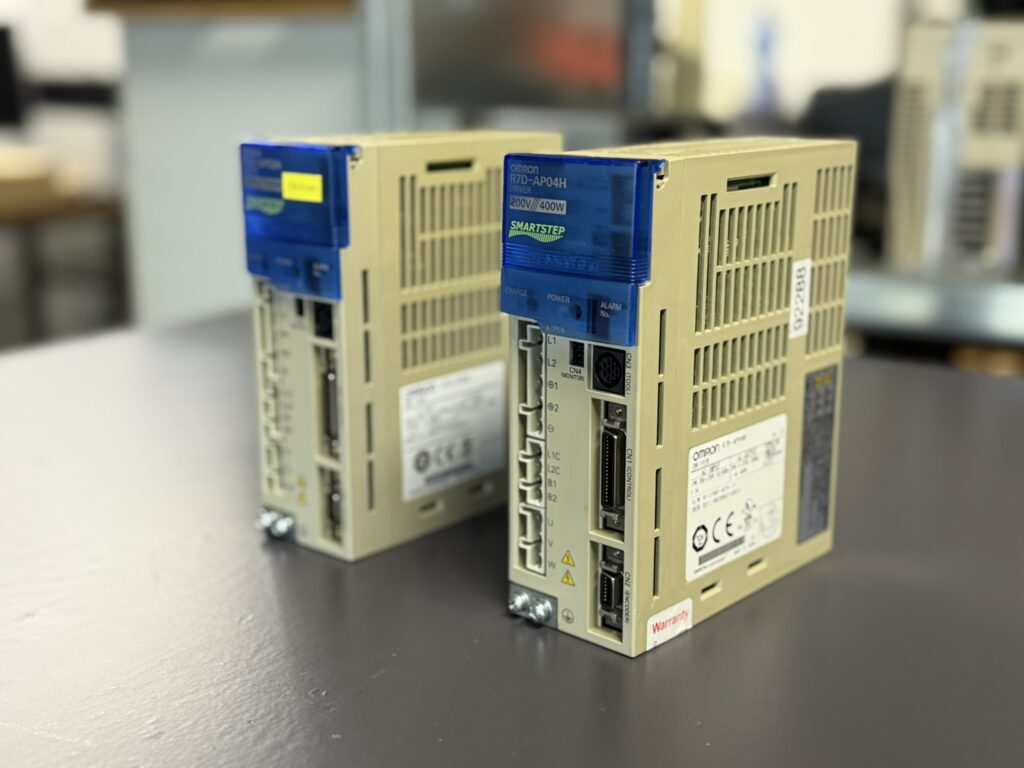
One of our customers encountered irregularities in the labelling and operation of purchased Omron R7D-AP04H and R7D-AP02H Servopacks. The main issues involved inconsistent version information and difficulties loading parameters. This case illustrates why a documented assessment before installation is worthwhile and why repairing a known original unit can be an alternative worth considering.
The Customer Case: Same Model Number, Different Starting Conditions
The customer uses several hundred units from this series. According to the customer’s account, some of the purchased replacement units had been relabelled from Version 11 to Version 22. Problems transferring parameters and recurring malfunctions occurred during commissioning or operation.
Altered labelling creates a significant problem: maintenance personnel plan the replacement using information that may not match the actual unit. Troubleshooting then starts from incorrect assumptions. A seemingly suitable spare part can require additional investigation while the equipment remains out of service.
The version numbers 11 and 22 mentioned in this case do not, on their own, allow a definitive assessment of technical differences or interchangeability. A reliable assessment requires considering the existing unit, the replacement unit and the machine’s requirements together.
Investigating Irregularities in Labelling
A replacement label or a cosmetically refurbished housing does not, by itself, prove that a unit is counterfeit. An irregularity becomes relevant when the advertised features, the unit’s identification and its actual configuration do not match. Likewise, a unit’s quality cannot be determined solely by its country of origin or price.
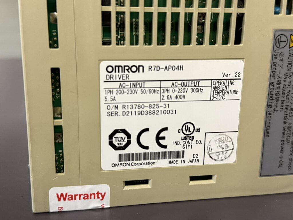
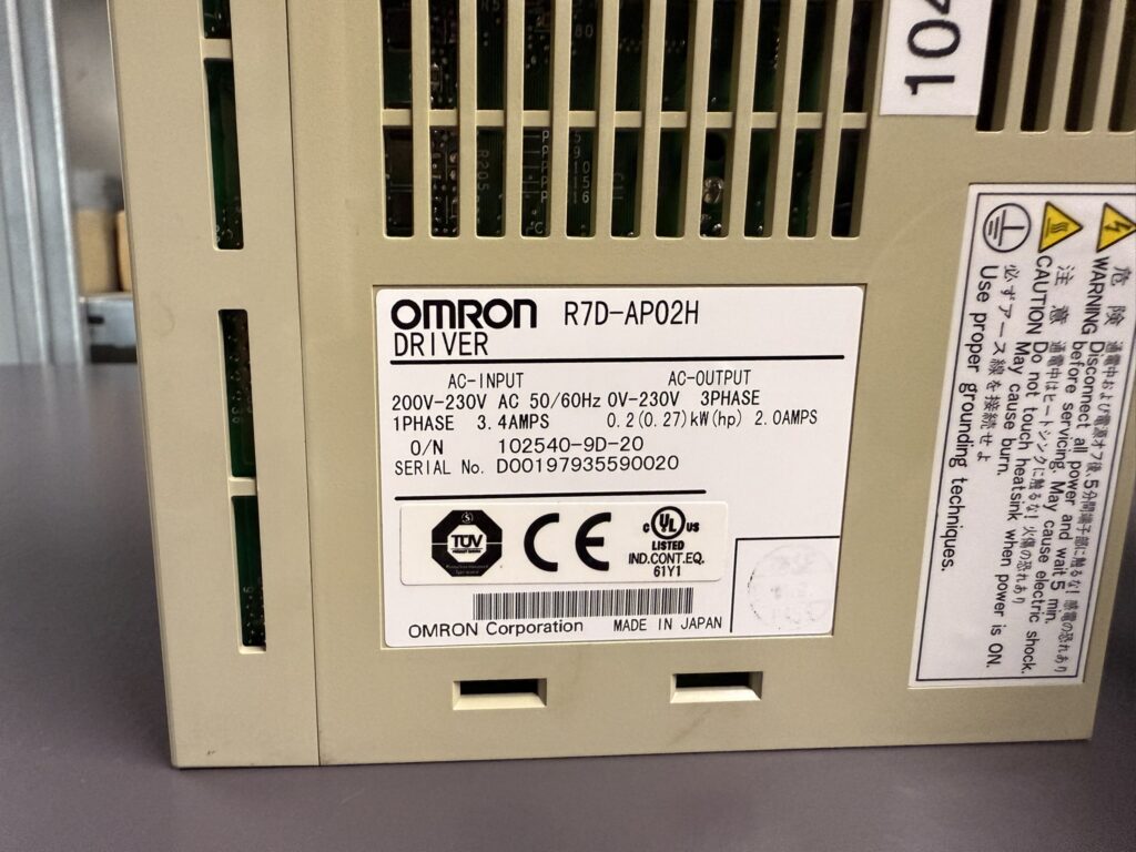
When purchasing a replacement, it is advisable to request complete, clearly legible photographs of the actual unit. These should show the model designation, version information, nameplate and connections. Delivery documents and information about previous repairs should be clearly traceable to that unit. Resolving outstanding questions before installation is more useful than troubleshooting during a production stoppage.
It is also important to distinguish between an untested used unit, a tested replacement unit and a documented overhaul. These descriptions represent different scopes of work. A clean exterior says little about which electrical tests have actually been performed.
Systematically Narrowing Down Parameter Problems
If a parameter set cannot be transferred, the exact sequence should first be recorded. Does the connection fail, is the transfer interrupted, or are individual values rejected? Does the transfer appear to succeed, but the machine subsequently behave differently? These observations lead to different diagnostic approaches.
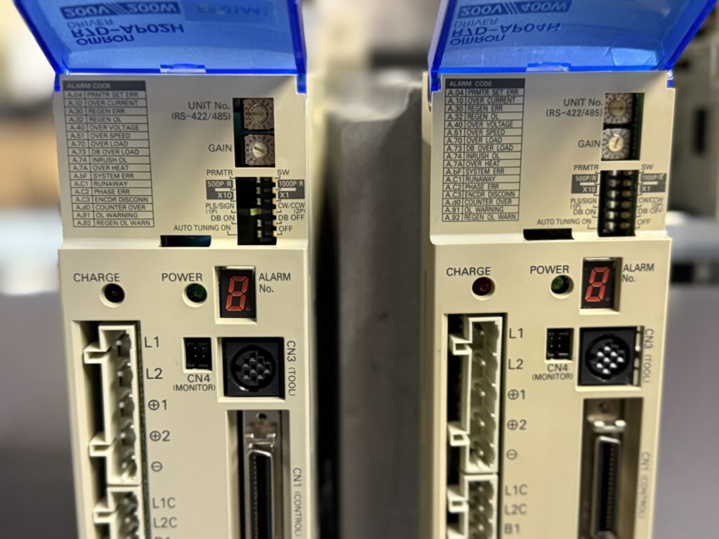
As a general diagnostic recommendation, first check the connection being used, the operating tool, the origin of the parameter file and whether the data is assigned to the correct unit. A saved data set must be suitable for the intended application. Existing switch positions should also be photographed and documented together with the settings.
A parameter problem does not, by itself, prove an internal electronics fault or tampering. Conversely, a successful data transfer does not automatically confirm that the unit operates correctly under working conditions. Testing must therefore cover the configuration as well as electrical and dynamic operation.
Repairing the Known Unit as an Alternative
If an original unit has been used in the machine for a considerable time, its association with that equipment is already known. This can provide a useful starting point for a repair. A technical assessment is needed to evaluate repairability, condition and the work required.
Our repair process for Omron drive technology includes fault analysis, cleaning, preventive overhaul based on the findings, parameter verification and final testing. The work required on an individual unit depends on its condition. A description of the process does not replace an individual diagnosis.
When examining older electronics, areas to investigate may include the power supply, power electronics, connectors and signal processing. Component replacement should be supported by a traceable finding or a justified overhaul plan. The cause, the work performed and the test result need to be consistent with one another.
What a Meaningful Functional Test Should Cover
The documented scope of testing is important when assessing a repair. A unit that powers up has not necessarily been tested in all operating states relevant to the machine. General test points may include repeated starts, changes of direction, different motion sequences and observing behaviour as the unit warms up.
The test setup should suit the intended application. It is equally important to document which peripheral equipment was used and under what conditions testing took place. This makes it easier to determine later whether a recurring fault originates in the drive itself or in its interaction with the motor, cabling, controller and mechanics.
A test bench can assess many functions. Final commissioning on the machine nevertheless remains a separate step, because this is where the actual load and machine-specific sequences come together. A clear description of the tests performed is therefore more useful to the operator than a general statement such as “tested”.
Documenting Spare Parts and Settings in Advance
For equipment with many similar drives, it is advisable to maintain a unit register recording the associated machine, full model number, version information and backed-up parameter set. Replacements and repairs should remain traceable in this register. A prepared replacement unit can then be selected more accurately, and commissioning can be planned more effectively.
If irregularities occur only intermittently, brief records can help: When did the fault occur, was the machine cold or already warm, and which movement was being performed? Photographs or a short video of the display can support subsequent diagnosis. This information helps focus the investigation on the actual symptoms.
Correct Configuration and Documented Testing Are Essential
This case shows that a matching model number alone is not a reliable basis for replacing a unit. With Omron R7D-AP04H and R7D-AP02H drives, identification, actual configuration and machine settings should be checked together. Professional repair of the existing unit can be a sensible option when supported by the findings and subsequent functional testing.
Price, Lead Time and Further Information
Current information on price and lead time is available on the product pages for the Omron R7D-AP02H Ver. 22 and the Omron R7D-AP04H Ver. 22. Before replacing a unit, the version offered there must be checked against your existing configuration.
Further information about our repair services for Omron servo drives and servo motors is available in our Omron service section. Please feel free to contact us if you have any questions about your Omron drive technology, the unit version or a specific fault.
Technical Section: Omron R7D-AP02H and R7D-AP04H
Technical Specifications
The electrical ratings are taken from the linked industrypart product information. The nameplate of the specific unit remains the governing reference. Note the distinction between the single-phase mains input and the three-phase motor output.
| Feature | R7D-AP02H | R7D-AP04H |
|---|
| Manufacturer | Omron | Omron |
| Device type | AC servo drive | AC servo drive |
| Series | SMARTSTEP A | SMARTSTEP A |
| Power class | 200 W | 400 W |
| Mains input | Single-phase, 200–230 V AC | Single-phase, 200–230 V AC |
| Mains frequency | 50/60 Hz | 50/60 Hz |
| Input current according to product information | 3.4 A | 5.5 A |
| Motor output | Three-phase, 0–230 V AC | Three-phase, 0–230 V AC |
| Output current according to product information | 2.0 A | 2.6 A |
| Output frequency according to product information | 300 Hz | 300 Hz |
| Command input | Pulse input | Pulse input |
| Manual | Omron I533-E1-04 | Omron I533-E1-04 |
Input and output currents refer to different sides of the converter and must not be treated as equivalent. The power rating is used to identify the unit’s power class; it does not indicate the machine’s total mains power requirement.
Operating Environment and Compatible Equipment
Typical applications include positioning tasks in assembly, handling and production equipment. Before replacement, the full motor model, its feedback system, the wiring and the machine-specific settings must be checked for compatibility. A higher power class does not automatically make a unit a suitable replacement for a smaller drive.
No specific machine model or controller is identified for the customer case described here. Versions 11 and 22 should be treated as additional identifying information; they do not replace a check of suitability for the specific machine.
Functional Description
The units process pulse commands and encoder feedback. CN4 provides analogue monitor signals, not an analogue command input.
In general, an AC servo drive converts mains energy into a controlled motor current. The requested motion is compared with the feedback from the motor. For troubleshooting, this provides a practical way to separate the areas of investigation: power supply, command transmission, feedback and mechanical load must each be considered. A fault in the overall system does not necessarily originate in the servo drive itself.
Components and General Inspection Areas
The following overview describes general functional areas of a servo drive and possible starting points for a specialist repair workshop. It is not a bill of materials for the units shown. PCB designations, quantities and specific component defects are not documented for this case.
| Functional area | Purpose | General inspection approach |
|---|
| Input and DC link | Energy intake and buffering | Assess the supply and component condition |
| Power electronics | Controlled motor supply | Examine the output stage and its drive circuitry |
| Internal power supply | Supply to the electronics | Check stability during startup and warming |
| Control and signal processing | Processing commands and feedback | Check configuration and signal paths |
| Connections and heat dissipation | Electrical connection and cooling | Check contact condition, contamination and thermal irregularities |
Alarm Messages and Troubleshooting
Selection from the Omron I533-E1-04 manual, Chapter 5. The measures are abbreviated; consult the manual for model-specific details. The table describes possible faults in this series, not alarms confirmed in this customer case.
| Code | Original designation | Meaning | Possible cause | Action |
|---|
| A.04 | Parameter setting error | Incorrect setting | Value outside the permitted range | Correct the settings |
| A.10 | Overcurrent | Excessive current | Short circuit | Check the motor cable |
| A.30 | Regeneration error | Regenerative circuit fault | Defective regenerative circuit | Inspect/replace the drive |
| A.32 | Regeneration overload | Regenerative overload | Excessive braking energy | Check the system sizing |
| A.40 | Overvoltage/undervoltage | DC voltage outside the permitted range | Mains supply deviation | Check the supply |
| A.51 | Overspeed | Excessive speed | Unsuitable command value | Correct the command value |
| A.70 | Overload | Excessive load | Mechanical blockage | Remove the blockage |
| A.73 | Dynamic brake overload | Braking overload | Frequent braking | Reduce braking frequency |
| A.74 | Inrush resistance overload | Inrush resistor overloaded | Frequent mains switching | Reduce switching frequency |
| A.7A | Overheat | Excessive temperature | Insufficient heat dissipation | Check installation/cooling |
Before resetting an alarm, switch off RUN and eliminate the cause. Work on the drive must be carried out by qualified personnel.
Diagnostic Notes on the Main Issue Described
The documented main issue concerns correct unit identification and parameter transfer. No specific alarm indication is documented for this case. The alarms listed above therefore provide general guidance for troubleshooting this series.
The following steps are recommended for the investigation:
- Document the existing unit and replacement unit separately: model number, version marking, nameplate and origin.
- Describe the parameter transfer problem precisely and record any error messages in full.
- Check that the parameter backup, transfer method and configuration correspond to the machine.
- If operation is unstable, include the power supply, cables and contact points in the investigation.
- If identification markings conflict, have a specialist determine the actual configuration.
- After repair, document the scope and outcome of testing and recommission the machine in a controlled manner.
Preventive Measures
The control cabinet and heat dissipation should be checked according to contamination levels and operating conditions. Maintenance should include cables, connectors and strain relief. Parameter records and the assignment of units to machines should be updated after changes.
For frequently used assemblies, it is useful to assign tested replacement units clearly to suitable applications before a failure occurs. Recurring faults should be documented together with the operating state and exact display indication. New behaviour following a unit replacement should prompt a check of both the replacement unit and its configuration.