12.07.2026 by Viktor Siebert
CNC Failure Caused by Sporadic Alarm 10 on the Okuma VACIV-D6 Spindle Drive
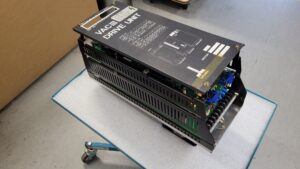
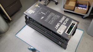
An Okuma VACIV-D6 spindle drive arrived at our workshop with a fault that was difficult to isolate: Alarm 10 appeared occasionally during machine operation. After restarting, the CNC machine could sometimes be operated again, but the fault returned without any reliable warning.
Sporadic faults in spindle drives are especially problematic for production companies. As long as the system is operating, the fault often cannot be reproduced immediately. If it occurs during machining, the spindle is stopped and the active program is interrupted. In addition to the actual machine downtime, workpieces, tools and firmly scheduled production times may also be affected.
The provided Okuma manual describes Alarm 10 as “Motor cable overcurrent.” This refers to an instantaneous overcurrent event detected within the motor circuit of the VAC drive system. The alarm has alarm level 1a and processing level 1. The system switches off the motor current and allows the motor to coast freely.
When Alarm 10 occurs only occasionally, it is therefore not sufficient to examine only the power section of the spindle drive. The spindle motor, motor cable, all plug connections, insulation to ground and the current detection circuitry inside the drive must also be considered.
Initial Diagnosis of the Okuma VACIV-D6
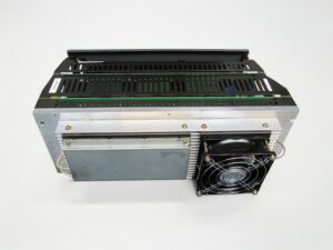
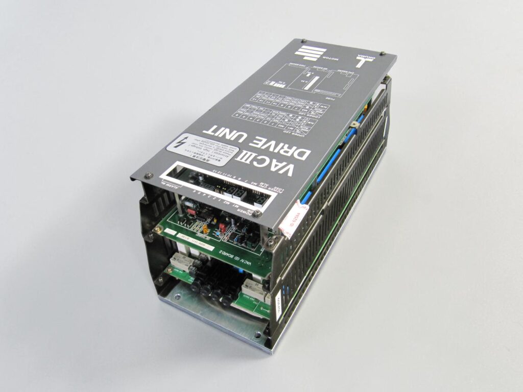
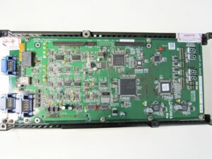
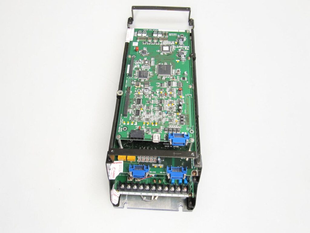
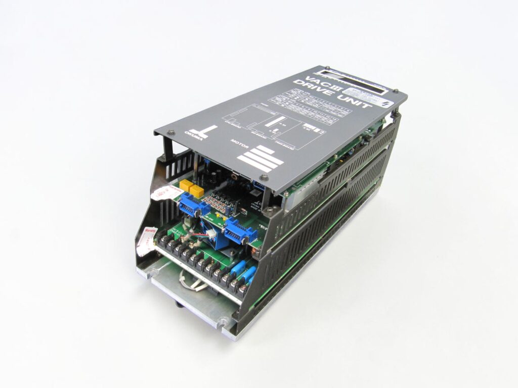
The inspection began with a complete visual examination of the unit and its individual assemblies. According to the available inventory data, the VACIV-D6 consists of several functionally separated boards and a power section.
| Assembly | Board designation | Model designation | Manufacturer No. | Quantity |
|---|
| Control board | VAC IV CPU Board | 06011-10030-10 | A006-1510 | 1 |
| Power board | VAC IV GD Board 2 | 06011-21030 | A006-1511 | 1 |
| Interconnection board | Not specified | E4809-770-077 | Not specified | 3 |
| Power board | Power Board | E4809-820-001-B | 1006-1212 | 1 |
| Power section | D6 | Not specified | Not specified | 1 |
The following areas were checked first:
- Discoloration, thermally stressed areas and damaged conductor tracks
- Contamination between the individual assemblies
- Condition of connectors and interconnection boards
- Contact points between the CPU board, gate-drive board and power board
- DC bus and power-carrying connections
- Power semiconductors and their drive circuitry
- Current measurement and current feedback
- Power supply to the control electronics
- Insulation clearances and possible conductive deposits
- Mechanical condition of assemblies and solder joints
In the case of a sporadic overcurrent alarm, a purely static measurement is often insufficient. A semiconductor or drive stage may operate normally when cold and only become unstable under temperature, higher motor current or rapid load changes.
The Okuma manual distinguishes between normal operating indication and fault operation. Under normal conditions, the M1, M2 and M3 status LEDs are switched off. In the event of a fault, at least one of these LEDs lights or flashes. The fault is additionally shown as a two-digit number on the seven-segment display of the control board. With Alarm 10, the indicators assigned to the power circuit illuminate according to the fault logic.
Meaning of Alarm 10
| Feature | Information from the documentation |
|---|
| Alarm number | 10 |
| English designation | Motor cable overcurrent |
| Meaning | Instantaneous overcurrent in the motor circuit |
| Alarm level | 1a |
| Processing level | 1 |
| Drive reaction | Motor current is switched off |
| Motor behavior | Motor coasts freely |
| Assigned status indication | IOCM |
| Affected area | Power circuit, motor cable or connected load |
The term “Motor cable overcurrent” does not automatically mean that only the motor cable is defective. The drive detects a current that exceeds the permissible detection range. The technical cause may be located in several different areas:
- Short circuit or temporary connection between two motor phases
- Insulation fault from one motor phase to PE or the motor housing
- Damaged motor cable
- Contaminated or damp motor connector
- Insulation problem in the spindle motor
- Fault in the power section of the VACIV-D6
- Unstable gate drive
- Faulty current detection
- Contact problem between internal boards
- Thermally unstable electronic components
Actual Fault Cause and Technical Assessment
Because the alarm occurred only occasionally, there was no permanently low-resistance connection at the output. A permanent short circuit would normally have triggered the fault reproducibly during power-up or immediately upon the first drive command.
The fault pattern therefore indicated an intermittent disturbance. Such faults may depend on load, motor speed, temperature or the switching state of the power stage.
The diagnosis focused on the following possible fault chains:
- A component inside the power section changes its electrical characteristics as it heats up.
- The current detection circuit temporarily reports an impermissibly high motor current.
- An unstable gate drive causes an incorrect switching event in the power semiconductors.
- A contact problem between the GD board, power board and power section interrupts or distorts drive signals.
- An aged power supply affects the control electronics or the driver stages.
- Conductive contamination or weakened insulation clearances cause a fault only under certain voltage and temperature conditions.
Without an additional inspection of the motor and motor cable, however, an external fault cannot be completely ruled out. If the alarm reappears after installation, the motor insulation, motor cable and plug connections in the machine must also be checked.
The provided manual clearly assigns Alarm 10 to instantaneous overcurrent in the motor circuit. Alarm 11, by contrast, describes a short circuit in one arm of the inverter bridge. This distinction is important for diagnosis: Alarm 10 initially describes the detected current event, while Alarm 11 explicitly refers to a bridge short circuit inside the inverter.
Repair Measures
Since no detailed list of the electronic components actually replaced is available, no specific semiconductors, capacitors or resistors are presented here as having been renewed.
Professional processing of an Okuma VACIV-D6 with this fault pattern nevertheless includes the following work steps:
- Complete dismantling of the accessible assemblies
- Cleaning of the boards and power components
- Inspection of all plug connections
- Testing of the three E4809-770-077 interconnection boards
- Examination of the VAC IV CPU Board 06011-10030-10
- Testing of the VAC IV GD Board 2 with number 06011-21030
- Inspection of the Power Board E4809-820-001-B
- Electrical testing of the D6 power section
- Inspection of the drive signals between the CPU board and gate drive
- Testing of internal supply voltages
- Examination of the current-measurement and protection circuits
- Thermal testing of suspicious assemblies
- Rework of suspicious solder and contact points
- Final insulation and safety inspection
Particular attention was paid to the connection between the control circuitry, gate-drive section and power stage. Reliable control of the power stage requires the switching commands from the CPU board to be transferred cleanly and processed correctly by the GD board.
Even small contact resistances, aged contact surfaces or thermally stressed solder joints can produce faults in an older spindle drive that remain invisible under no-load conditions.
Diagnosis of the External Motor Circuit
Before the Okuma VACIV-D6 is returned to service, the machine should additionally be inspected in the following areas:
| Test point | Procedure | Background |
|---|
| Motor cable U, V, W | Check continuity and phase resistances | Detect interruptions and contact problems |
| Insulation to PE | Disconnect motor and cable from the drive and test appropriately | Rule out ground faults or weakened insulation |
| Motor connector | Inspect for oil, moisture, coolant and contamination | Conductive deposits may trigger overcurrent |
| Terminal points | Check screws and contacts | Loose connections cause heating and arcing |
| Spindle motor | Compare winding resistances | Phase deviations may indicate winding damage |
| Mechanical load | Inspect spindle, bearings and drive train | Mechanical stiffness increases motor current |
| Shielding and grounding | Check cable routing and PE connections | Prevent interference with current detection |
An insulation test must not be carried out through the connected electronics of the spindle drive. The motor and motor cable must be professionally disconnected from the VACIV-D6 before testing.
Final Inspection and Return Shipment
After completion of the work, the Okuma spindle drive was reassembled and prepared for functional testing. During the final inspection, the assemblies were not assessed only in the powered-on state. The decisive factor was monitoring the drive across different operating and temperature conditions.
The test included:
- Controlled activation of the control voltage
- Checking the POWER, LOSS and CPUALM indicators
- Checking the seven-segment display
- Monitoring the operating-status LEDs
- Enabling the power section
- Testing the motor-circuit drive
- Switching between different speed and load conditions
- Repeated acceleration and deceleration cycles
- Temperature monitoring of the power electronics
- Extended operating phase to detect sporadic faults
- Repeated start and stop sequences
According to the manual, the POWER LED indicates that the VAC drive control supply is present. The LOSS LED indicates that a voltage in the arithmetic circuit is outside specification. The red CPUALM indicator marks a problem in the calculation or control circuit. The other LEDs serve as input and output indicators during normal operation and help isolate the alarm cause in the event of a fault.
The unit was approved for return shipment only after stable operation throughout the complete test period.
Price and Delivery Time for Okuma VACIV-D6 Drive Unit
For more information about our Okuma repairs, please click here.
📞 Feel free to contact us if you have any questions regarding your Mitsubishi drive technology. Our experienced team is always ready to provide you with expert advice and support.
Technical Data of the Okuma VACIV-D6
| Technical feature | Documented information |
|---|
| Manufacturer | Okuma |
| Device designation | VACIV-D6 |
| Alternative spellings | VAC IV-D6, VAC IV D6, Okuma D6 Spindle Drive |
| Device class | Spindle Drive Unit, CNC Drive, Spindle Amplifier |
| Function | Control and regulation of a VAC spindle motor |
| Axes | Spindle drive, partly with C-axis function depending on system configuration |
| Control board | VAC IV CPU Board 06011-10030-10 |
| Control board manufacturer No. | A006-1510 |
| Gate-drive board | VAC IV GD Board 2, 06011-21030 |
| Gate-drive manufacturer No. | A006-1511 |
| Power board | E4809-820-001-B |
| Power board manufacturer No. | 1006-1212 |
| Interconnection boards | E4809-770-077, three units in total |
| Power section | D6 |
| Diagnostic display | Two-digit seven-segment display |
| Status indicators | POWER, LOSS, CPUALM, M1, M2, M3 and LEDs 1 to 13 |
| Alarm transmission | Alarm data is transmitted to the NC and displayed on the CRT |
| Voltage | Not specified in the provided document extract |
| Output current | Not specified in the provided document extract |
| Output power | Not specified in the provided document extract |
| Frequency range | Not specified in the provided document extract |
| Software version | Not specified |
| Weight | Not specified |
| Protection class | Not specified |
Operating Conditions
The uploaded documentation does not contain a complete specification of the permissible operating conditions for the VACIV-D6. Therefore, no temperature, humidity or altitude values from other device series are adopted.
| Operating condition | Information |
|---|
| Permissible ambient temperature | Not stated in the provided VAC document |
| Storage temperature | Not stated |
| Relative humidity | Not stated |
| Permissible installation altitude | Not stated |
| Protection rating | Not stated |
| Installation environment | Control cabinet of a CNC machine tool |
| Cooling | Adequate air circulation and unobstructed cooling paths required |
| Contamination protection | Protection from oil mist, coolant, dust and metal particles required |
| Grounding | Reliable protective-earth and machine-ground connection required |
Regardless of the missing numerical values, the spindle-drive environment should be dry, clean and sufficiently cooled. Contaminated cooling paths and conductive deposits increase the thermal and electrical stress on the assemblies.
Interaction with Other Devices
The following system relationships can be derived from the provided documentation:
- Okuma CNC control with CRT or operator panel
- VAC spindle motor
- Motor cable between VACIV-D6 and spindle motor
- Speed or position feedback
- Machine enable and machine-ready signal
- Emergency-stop signal
- Winding-changeover signals
- Torque limitation
- High-speed and low-speed ranges
- C-axis function, where provided by the machine
- Regenerative main circuit
- External contactors for winding changeover
The normal status indication in the manual includes the following input and output signals:
| Signal | Meaning |
|---|
| MS ON | Main-circuit charging start command |
| SFR | Motor power-circuit supply or enable |
| WCHG | Winding-changeover command |
| TLMC | Torque-limit command |
| MRDY | Machine ready |
| EMR | Emergency stop |
| AWCHG | Winding changeover completed feedback |
| HMSCHG | High-speed range magnet or contactor signal |
| LMSCHG | Low-speed range magnet or contactor signal |
| ZERO | Zero-speed signal |
| AGRE | Speed-agreement signal |
| SRDY | Operation-ready signal |
Functional Description
The Okuma VACIV-D6 is a spindle drive for CNC machine tools. Its task is to process the electrical energy so that the connected VAC spindle motor can be controlled according to the commands of the CNC.
The VAC IV CPU Board processes the control and feedback signals. These include speed commands, machine enables, protection messages and status information. The GD board controls the power section. The power board and D6 power section switch the currents required by the motor.
During operation, the system monitors, among other things:
- Motor speed
- Speed command
- Motor current
- Power circuit
- DC bus voltage
- Input voltage
- Phase condition
- Heat-sink temperature
- Motor overload
- Resolver or PG signals
- Communication with the NC
- RAM and CPU functions
- Winding changeover
The manual distinguishes between two alarm groups. Some alarms are detected directly in the VAC drive. These include power-circuit alarms such as motor overcurrent, inverter-bridge short circuit, overvoltage or undervoltage. Other messages are detected by the NC, such as start, communication or file errors.
Alarms detected directly in the VAC drive are shown both on the NC CRT and on the seven-segment display and corresponding status LEDs. Alarms detected only in the NC appear solely on the operator screen.
Operating Reaction of the Alarm Processing Levels
| Processing level | Reaction of the VAC system |
|---|
| 1 | Motor current is switched off immediately, motor coasts freely |
| 2 | Speed is reduced, motor is stopped, then current is switched off |
| 3 | External reaction is the same as level 2, but with different internal processing |
| 4 | Alarm changes to level 3 after 30 seconds |
Alarm 10 has processing level 1. For this reason, the motor current is switched off without controlled deceleration.
Alarm and Fault Codes of the Okuma VAC System
The following table is based on the alarm overview in the uploaded VAC manual. The reset information is formulated functionally because the supplied document shows alarm levels but does not list a separate reset button for every code. The cause must be eliminated before resetting.
| Alarm | Fault name | Meaning | Reset | Corrective action |
|---|
| 01 | P.G. count error | Detected PG count exceeds the PBU data | After eliminating the cause and restarting | Check PG, feedback and PBU data |
| 02 | Excessive motor speed | Actual motor speed is too high | After standstill and elimination of the cause | Check speed control and feedback |
| 03 | APA speed | Detected spindle speed is too high | After eliminating the cause | Check speed detection and control |
| 04 | CON speed | Velocity command or feed data is too high | After correction | Check NC command and communication timing |
| 05 | DIFF over | Excessive deviation in C-axis mode | After correction | Check C-axis control and mechanics |
| 06 | Resolver error | Resolver signal is not output | After repair | Check resolver, cable and input circuit |
| 07 | RAM parity error | RAM cannot be read from or written to correctly | Restart after inspection | Check CPU board and RAM section |
| 08 | Communication error | Communication between VAC and NC is interrupted or faulty | After communication check | Check cable, connectors and NC |
| 09 | Command error | Transmitted command is undefined or cannot be executed | After command correction | Check NC data and program |
| 10 | Motor cable overcurrent | Instantaneous overcurrent in the motor circuit | After eliminating the overcurrent | Check motor cable, motor, insulation, power section and current measurement |
| 11 | Inverter bridge short | Short circuit in one arm of the inverter bridge | Do not re-enable before the cause is clarified | Check power semiconductors and gate drive |
| 12 | Regenerator IGBT short | Overcurrent in the regenerative main circuit | After repair | Check regeneration IGBT and circuitry |
| 13 | Power circuit overvoltage | Excessive DC voltage in the main circuit | After voltage has discharged | Check mains supply and regeneration circuit |
| 14 | Input voltage drop | Three-phase input voltage is below specification | After stable supply is restored | Check incoming supply, contactor and wiring |
| 15 | Open phase | One phase of the three-phase input is missing | After restoring all phases | Check fuses, contactors and terminals |
| 16 | Loss of arithmetic circuit power | Control voltage on the control board is too low | After repair | Check internal power supply |
| 17 | Power circuit low voltage | DC voltage in the main circuit does not rise | After inspection | Check charging circuit and power circuit |
| 18 | INT loop error | Internal interrupt processing is not correct | Restart after diagnosis | Check CPU board and interference influences |
| 19 | Motor overload | Motor temperature exceeds permissible value | After cooling and eliminating the cause | Check load, motor and cooling |
| 20 | Heat sink overheat | Drive heat-sink temperature is too high | After cooling | Check cooling, fan and heat sink |
| 21 | Data setting abnormal | PBU data or online parameters are outside the valid range | After correction | Check data sets and parameters |
| 22 | Internal velocity command too fast | Internal speed command is too high | After correction | Check control parameters and command value |
| 23 | P.G. error | Magnetic pulse-generator signal is missing | After repair | Check PG, cable and connector |
| 24 | P.G. marker latch data error | Marker count exceeds the PBU data | After correction | Check marker, PG and PBU data |
| 25 | Cycle over error | Internal VAC cycle error | Restart after diagnosis | Check CPU board and sequence processing |
| 26 | Watchdog error | Watchdog timer is not reset | Restart after diagnosis | Check CPU board and power supply |
| 27 | A/D access alarm | A/D access occurs during conversion | After repair | Check A/D circuit and CPU board |
| 28 | Master CPU error | Hardware or processing error of the master CPU | After diagnosis | Check or repair CPU board |
| 29 | Slave CPU error | Hardware or processing error of the slave CPU | After diagnosis | Check or repair CPU board |
| 30 | Excessive velocity deviation error | Motor-speed deviation is too large | After eliminating the cause | Check motor, feedback, load and control |
| 31 | Winding changeover error | Winding-changeover contactor is not switched on | After repair | Check changeover contactors, drive and feedback |
| 32 | RAM error | RAM contents cannot be cleared at power-up | Restart after diagnosis | Check RAM and CPU board |
Preventive Measures for the Machine Operator
Maintenance of an older Okuma VACIV-D6 should not begin only after the spindle drive has failed completely.
| Measure | Recommendation |
|---|
| Inspect control-cabinet filters | Regularly check for contamination and airflow |
| Clean cooling paths | Remove dust, oil mist and metal particles |
| Inspect plug connections | Check for heating, oxidation and loose contacts |
| Inspect motor cable | Prevent abrasion, crushing and oil exposure |
| Inspect motor connector | Keep dry and free from coolant |
| Monitor spindle motor | Observe operating noise, temperature and current consumption |
| Document alarm history | Record speed, load and operating condition when the fault occurs |
| Inspect fans | Replace stiff or noisy fans at an early stage |
| Check grounding | Ensure uniform and low-resistance PE connections |
| Clean electronics | Only carry out professionally and with power disconnected |
In the case of Alarm 10, information about the exact time of occurrence is particularly useful. Relevant details include whether the alarm appears during start-up, at a certain speed, during acceleration, at tool contact or only after a longer operating period.
Conclusion
The occasional Alarm 10 on the Okuma VACIV-D6 is a serious overcurrent alarm in the motor circuit. The cause may be located inside the spindle drive as well as in the connected motor, motor cable or plug connections.
A reliable repair therefore requires more than replacing a single board. Only a combined assessment of the CPU board, gate-drive board, power board, D6 power section, current detection and external motor circuit provides a dependable diagnosis.
Especially with sporadic faults, extended testing under changing operating conditions is decisive. Only in this way can temperature-dependent and load-dependent faults be detected that remain inconspicuous during a brief power-on test.