25.01.2026 by Viktor Siebert
Repair of an Okuma Servo Drive Unit MIV08-1-P1 (1006-2219)
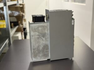
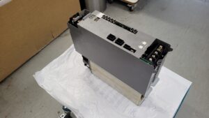
Incoming condition and initial assessment
The Okuma Servo Drive Unit MIV08-1-P1 was received with the information that the machine no longer initializes correctly during startup. According to the customer, different fault patterns occurred depending on which axis was tested. This information is already an important indication in Okuma systems, as faults cannot always be clearly assigned to a single assembly.
After visual inspection and documentation of the incoming condition, the unit was processed according to our incoming inspection checklist. This includes verification of serial numbers, comparison of assemblies, mechanical inspection, and an initial electrical baseline measurement without load.
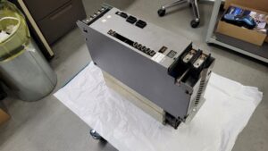
Test setup in an original Okuma machine
All further tests were deliberately carried out in an original Okuma machine rather than on a universal test bench. Only in this way can initialization sequences, servo handshakes, and the interaction between CNC, power supply, and MIV unit be realistically evaluated. External test environments may mask certain fault conditions or fail to trigger them altogether.
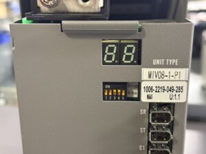
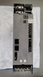
For the first test, the MIV unit was operated on the Z axis using an external motor. During initialization, the CNC immediately displayed an alarm with the letter “P”. At the same time, the 7-segment display on the MIV unit permanently showed the indication “3”. Initialization was not completed, and the system did not proceed any further.
This behavior indicates an internal fault state that occurs before the axis is actually enabled.
Comparative test on the Y axis
In the next step, the same MIV unit was tested on the Y axis. This test was deliberately performed to rule out a possible axis or motor-related issue. According to the customer, alarm 03 had previously occurred on this axis, accompanied by a DC bus alarm on the CNC side.
This fault could also be reproduced. This is a decisive point in the diagnostic process: when a fault occurs independently of the axis, the cause is very likely within the drive itself rather than in the motor, cabling, or mechanical components.
Systematic diagnosis according to checklist
Further analysis was carried out strictly according to our internal diagnostic checklist. First, the internal supply voltages were measured. Deviations in the stability of individual supply rails were observed under certain load conditions, particularly during the initialization phase.
Subsequently, the power stage was evaluated separately. It was noticeable that the system partially powers up but then transitions into an undefined internal state before a proper enable signal is issued. This behavior matches known fault patterns in aging power assemblies or unstable control circuitry.
Preventive repair and overhaul
Based on the measurement results, not only was the immediate fault addressed, but a preventive overhaul was also performed. Especially for MIV units of this generation, it is advisable not to limit repairs to a single issue but to proactively address known weak points.
The assemblies were completely disassembled, cleaned, and inspected. Thermally stressed components, critical interfaces, and contact-relevant areas were specifically reworked. The objective was not only to eliminate the current malfunction but to restore long-term operational reliability.
Final test and release
After repair, the MIV unit was once again tested in the original Okuma machine. Both initialization on the Z axis and operation on the Y axis were completed without errors. The CNC started up cleanly, the drive behavior was stable, and all internal states remained unremarkable even under load.
Only after multiple cold and warm starts and repeated axis movements was the unit approved for shipment.
Price and Delivery Time for Okuma Servo Drive Unit MIV08-1-P1 (1006-2219)
For more information about our Okuma repairs, please click here.
📞 Feel free to contact us if you have any questions regarding your Okuma drive technology. Our experienced team is always ready to provide you with expert advice and support.
Device data and core specifications
| Feature | Value |
|---|
| Model designation | MIV08-1-P1 |
| Part number (MPN) | 1006-2219 (also known as 1006-2219-050-257) |
| Device type | Inverter Unit / Servo Drive, 1st generation |
| Number of axes | 1 axis (single axis) |
| Rated power | 7.5 kW (approx. 10 HP) |
| Control board | ICB1 or E4809-770-107 |
| Manufacturer | Okuma |
| Series | MIV |
Electrical data
| Parameter | Value |
|---|
| DC bus voltage | 300 V DC (supplied by central power supply unit such as MPS or MPR) |
| Control voltage | 24 V DC |
| AC input voltage | Three-phase 200 V AC (via power supply unit) |
| Motor output | Three-phase U / V / W |
| Compatible motors | Okuma BL motors or PREX motors in the 7.5 kW class |
Design and cooling
| Feature | Description |
|---|
| Design | Modular inverter unit for control cabinet installation |
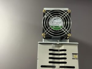
| Cooling | Integrated cooling system with heat sinks (radiant fins) |
| Fans | Internal and external fans for active heat dissipation |
| Heat dissipation | Convective and forced-air cooling |
Connections and interfaces
| Connection | Function |
|---|
| L1 / L2 / L3 | AC input via MPS/MPR power supply |
| +DC / -DC | DC bus connection (300 V DC) |
| U / V / W | Motor output terminals |
| CN1 / CN2 | Servo link, communication with CNC control |
| CN3 | Encoder or resolver connection |
| Front display | 7-segment LED for status and fault indication |
Display and diagnostics
| Element | Description |
|---|
| LED display | 7-segment display on the front |
| Function | Displays operating states, status codes, and alarm messages |
| Purpose | Quick diagnostics during initialization and operation |
Typical operating environment
| Area | Description |
|---|
| Machines | Okuma CNC turning and machining centers |
| Axes | Z, Y and additional feed axes |
| Operation | Multi-shift operation, high dynamics |
| Environment | Control cabinet, industrial environment |
Functional description
| Function | Description |
|---|
| Power conversion | Conversion of DC bus voltage for motor control |
| Control loops | Current, speed, and position control |
| Communication | Servo link to CNC |
| Protection functions | Overcurrent, overtemperature, DC bus monitoring |
Alarm Messages Okuma MIV Servo Drive
| Alarm code | Name | Description | Typical cause | Recommended action |
|---|
| 01 | Power Supply Unit Error | Error in the connected power supply unit | DC voltage fault, AC input error, internal PSU failure | Check mains supply, inspect or replace MPS/MPR |
| 02 | Converter Link Error | Communication error between MIV and power supply | Interrupted connection, timeout | Check converter link cable, replace MIV or PSU if required |
| 03 | Inverter DC Bus Voltage Error | DC bus voltage too high or too low | Power fluctuation, aged components | Check supply, inspect MPS/MPR or MIV |
| 04 | Motor Power Line Overcurrent | Overcurrent detected in motor power line | Motor short circuit, defective power stage | Check motor and power section |
| 05 | Inverter Overheat | Inverter temperature exceeded limit | Fan failure, contaminated heat sinks | Check cooling system, service MIV |
| 06 | Inverter Overload | Electronic thermal overload protection activated | Excessive mechanical load, incorrect parameters | Reduce load, verify servo data |
| 07 | Commercial Power Source Error | Input power voltage out of tolerance | Unstable supply, wiring issue | Check mains supply and cabling |
| 10 | Encoder Communication Error | Communication error with encoder | Encoder cable failure, noise interference | Check encoder and cabling |
| 12 | Encoder Initialization Error | Error during encoder initialization | Incompatible parameters, encoder fault | Inspect encoder or MIV |
| 13 | Inverter Bridge Error | Power device bridge error | Failed power semiconductor devices | Repair or replace MIV |
| 14 | Motor Overcurrent Error | Abnormal motor current detected | Short circuit, unstable power stage | Inspect motor and power electronics |
| 20 | Motor Overheat | Motor temperature exceeded limit | Continuous overload, cooling issue | Check operating conditions, inspect motor |
| 21 | Servo Link Communication Error | Communication failure between CNC and MIV | Damaged servo link cable | Check cable, MIV or FCP board |
Components
| Assembly | Designation | Function |
|---|
| Control board | ICB1 or E4809-770-107-F / 1006-2107 | Control logic |
| Power board | IVPB08-1 | Power electronics |
| Interface board | BTB71 | Internal signal routing |
| Power module | MIV08 | Energy conversion |
Conclusion
This repair case clearly demonstrates how important testing under real operating conditions is. Only operation in an original Okuma machine allows reliable diagnosis of initialization faults and axis-independent issues. Through preventive overhaul, not only was the immediate fault resolved, but the long-term operational reliability of the MIV servo drive was restored.