20.09.2026 by Viktor Siebert
Okuma MIV0404-1-B5 with Alarm 28: Y-Axis Failure Caused by Insufficient Cooling and a Defective Power Stage
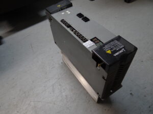
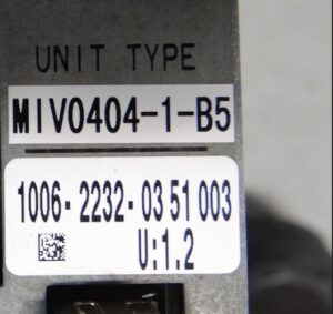
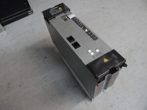
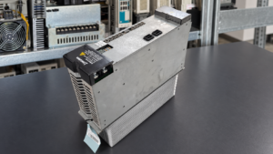
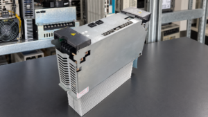
The Okuma Servo Drive Unit MIV0404-1-B5 with order number 1006-2232 arrived at our facility with an axis-specific fault. During testing on the CNC machine, the X-axis initially operated correctly. However, as soon as movement of the Y-axis was commanded, the drive shut down immediately and displayed Alarm 28.
With a dual-axis servo drive, this observation is particularly important for the diagnosis. If one axis operates and the second axis fails only when a movement command is issued, the general power supply is not the only area that must be considered. The separate power paths, motor control, feedback system, and the mechanical and thermal influences affecting the relevant axis must also be checked.
In this case, the investigation led to the power stage of the Y-axis. The fan was also identified as a critical part of the fault chain. Although it was still visibly rotating, it was heavily contaminated and no longer provided the required cooling performance. This initially made the defect easy to overlook. Over time, the thermal stress on the power electronics increased until the power stage eventually failed.
What Does Alarm 28 Mean on an Okuma MIV Servo Drive Unit?
In the available servo alarm list for the Okuma MIV series, Alarm 28 is designated as “DIFF over.” The alarm means that the position error within the position control loop has become excessively large. In simple terms, the actual detected axis position is no longer following the target value commanded by the control system with sufficient accuracy.
According to the manual, a detected position error is output together with the alarm. The possible corrective actions specified by Okuma include reducing inertia and friction resistance in the mechanical system and checking or replacing the MIV Unit or the motor.
These instructions show that Alarm 28 does not automatically indicate only one specific defect. A stiff mechanical system, a motor problem, faulty feedback, or an internal fault in the servo drive can all cause an excessive control deviation. The alarm must therefore not be addressed simply by replacing an arbitrary component. The conditions under which it occurs and whether only one of the two axes is affected are decisive for the diagnosis.
On the MIV0404-1-B5 examined here, the X-axis was operational. The Y-axis, by contrast, shut down immediately when movement was attempted. This behavior directed the diagnosis specifically toward the power path assigned to the Y-axis.
Differentiation from the System Alarm Also Listed as Number 28
In the Okuma documentation, the number 28 also appears in a table of internal system alarms. In that table, it is described as “Parity error” and refers to an error in CPU processing. This system alarm must be distinguished from Servo Alarm 28 “DIFF over.”
For this repair case, the servo alarm “DIFF over” is relevant because the shutdown occurred on one specific axis when a movement command was issued. Nevertheless, the complete display, including the alarm type, additional data, and affected axis, should always be documented during diagnosis. The number 28 alone, without further context, is not sufficient for a reliable identification.
Function of the Okuma MIV0404-1-B5
The Okuma MIV0404-1-B5 is a dual-axis Servo Drive Unit from the MIV series. In the available Okuma configuration documentation, order number 1006-2232 is assigned to the MIV0404-1 PU. The module is designed for two BL motor axes, each with a motor capacity of 4 kW.
The Drive Unit processes the target values supplied by the CNC control and regulates the current, torque, speed, and position of the connected servo motors. The movement commands from the control are compared with the returned position values. From this information, the power electronics generate the required motor currents for both axes.
Because two axes are combined in one module, certain assemblies may be shared, while the power outputs operate on an axis-specific basis. An internal fault in one power path can therefore allow one axis to continue operating while the second axis fails when movement is commanded.
The Fan Was Rotating but No Longer Provided Sufficient Cooling
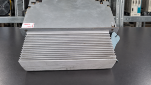
In this case, the fan was the original cause of the subsequent damage. Although it was still rotating, it was heavily contaminated and no longer moved enough air. This fault pattern is critical in practice because a visual inspection from a distance may suggest that the fan is still functioning correctly.
Effective cooling requires more than the fan wheel simply moving. Airflow, rotational speed, unobstructed air passages, and a clean heat sink are decisive. Deposits on the fan blades and inside the cooling channels reduce heat dissipation. At the same time, worn bearings or a weakened fan motor can prevent the fan from reaching its rated speed.
Under high load, the power stage generates considerable heat loss. If this heat is not dissipated reliably, the temperature of the power semiconductors and adjacent components rises. Prolonged thermal overload can accelerate aging and ultimately cause the power stage to fail. This exact fault chain was identified on the Okuma MIV0404-1-B5 in this case.
Incoming Inspection and Diagnosis on the CNC Machine
The reported fault was first isolated through a functional comparison. The X-axis could be moved and operated without the reported failure. On the Y-axis, however, Alarm 28 occurred immediately when a movement command was issued. This showed that the fault was dependent on load or control activity and did not occur merely when the module was switched on.
With this type of behavior, the alarm data, motor and encoder connections, mechanical condition of the affected axis, and the corresponding power output are among the items considered. Inside the unit, the cooling system, fan, air passages, power semiconductors, driver stages, power supplies, and connections between the assemblies are also checked.
The inspection of the MIV0404-1-B5 revealed a defective power stage. At the same time, the contaminated fan, which no longer provided sufficient airflow, was identified. This explained not only the current failure of the Y-axis but also how the damage had developed.
Repair of the Power Stage and Cooling System
The complete fault chain had to be considered during the repair. Repairing the power stage alone would not have been sufficient while the cause of the thermal overload remained. The fan and the inadequate cooling therefore had to be addressed in addition to the defective power electronics.
The affected areas were checked and the correct operation of the cooling system was restored. The exact types or individual designations of the replaced power semiconductors are not stated here because these details were not documented for this case. The decisive factor is the combination of repairing the failed power stage and eliminating the thermal cause.
After work on a dual-axis MIV module, both axis channels must be tested. In addition to enable signals and direction of rotation, current consumption, feedback, temperature development, alarm behavior, and operation during movement are relevant. A final positive test result after the repair was not documented separately for this report and is therefore not presented as a confirmed fact.
Why an Apparently Running Fan Can Still Be Dangerous
This repair case illustrates an often underestimated problem in industrial drive technology. Fans are frequently considered defective only when they stop completely. In reality, their cooling performance may have deteriorated significantly long before that point.
Dust, oil mist, and fine production residues accumulate on the blades, protective grilles, and heat sinks. This increases airflow resistance and reduces the volume of air moved. At the same time, an aged bearing can reduce the fan speed. The drive may still function under light load, while its temperature continues to increase during dynamic axis movements or longer machining cycles.
Preventive inspection should therefore do more than check whether the fan is rotating. Operating noise, airflow, contamination, and temperature behavior must also be considered. On older units, replacing a fan in time can be far less expensive than subsequently repairing a damaged power stage.
Preventive Information for Operators of Okuma MIV Drives
Control cabinet filters, fans, and heat sinks should be inspected and cleaned regularly, depending on operating hours and environmental conditions. Cooling performance can deteriorate much more quickly in environments with oil mist, conductive dust, or high ambient temperatures.
The actual airflow should be evaluated during inspection. A rotating fan wheel is not proof of sufficient cooling. Unusual operating noise, delayed startup, fluctuating speed, or noticeably weaker airflow are indications that replacement may be necessary.
If an alarm occurs only after a certain operating period or exclusively during movement of one axis, the conditions should be documented as accurately as possible. This includes the complete alarm display, affected axis, operating state, previous operating time, and commanded movement. These details help distinguish between mechanical, motor, encoder, and Servo Drive Unit faults.
Conclusion
On the Okuma MIV0404-1-B5 with order number 1006-2232, the X-axis operated while the Y-axis shut down immediately with Alarm 28 when movement was commanded. The Okuma alarm list describes this servo alarm as “DIFF over,” meaning that the position error is excessively large.
The diagnosis revealed a defective power stage. The fault chain originated with a heavily contaminated fan that was still rotating but no longer provided sufficient cooling performance. The continuing thermal stress eventually damaged the power electronics.
This case demonstrates why the cooling system of older Servo Drive Units must not be checked only superficially. Identifying a weak or contaminated fan at an early stage can help prevent costly secondary damage to the power stage.
Price, Lead Time and Further Information
Current information on the price and lead time of the Okuma Servo Drive Unit MIV0404-1-B5 with order number 1006-2232 can be found on the corresponding product page: https://www.industrypart.com/products/okuma-miv0404-1-b5-1006-2232-servo-drive-40979.html
Further information about our repair services for Okuma servo and spindle drives is available here: https://www.industrypart.com/okuma-drives
📞 Please feel free to contact us if you have any questions about your Okuma drive technology or a specific fault. Our team will be pleased to assist you with the technical assessment, repair, and testing of your unit.
Technical Block: Okuma MIV0404-1-B5 / 1006-2232
Technical Specifications
| Feature | Technical Information |
|---|
| Manufacturer | Okuma |
| Model | MIV0404-1-B5 |
| Alternative designation | MIV04041B5; base series unit MIV0404-1 PU |
| Article or order number | 1006-2232 |
| Device type | Dual-axis Servo Drive Unit / Inverter Unit |
| Number of axes | 2 |
| Compatible motor type | Okuma BL and PREX servo motors according to the product page; the supplied configuration documentation lists the MIV0404-1 for BL motors |
| Power rating | 4 kW per axis, equivalent to 5.3 hp per axis |
| Input voltage | 300 V DC from the MPS/MPR Power Supply according to the product page |
| Control voltage | 24 V DC according to the product page |
| Current | Not specified in the available documentation |
| Cooling | Active fan cooling; in this repair case the fan was contaminated and did not provide sufficient airflow |
| Control environment | Okuma CNC with MIV servo system |
| Year of manufacture | Not specified |
| Dimensions | Not specified |
| Weight | Not specified |
| Manual reference | Okuma 4742-E, Section 1 Inverter Unit (MIV Unit), configuration and alarm tables |
Operating Environment and Compatible Equipment
The MIV0404-1-B5 Servo Drive Unit is used within an Okuma CNC drive system to control two servo axes. The available Okuma configuration documentation assigns order number 1006-2232 to a dual-axis MIV0404-1 Inverter Unit for BL motors. An applicable motor capacity of 4 kW is specified for each axis.
Before replacing a module, the complete model designation, suffix, hardware version, control board, parameters or servo data, and machine configuration must be checked. The same order number alone does not automatically prove that every version can be used in every machine without further adaptation.
Functional Description
The MIV0404-1-B5 converts movement commands transmitted by the CNC into regulated motor currents for two servo axes. In position control, the system compares the target position with the returned actual position. Torque and speed commands for the relevant axis are generated from the resulting deviation.
The power electronics supply the motors according to demand. Feedback from the motor or position encoder enables continuous regulation and monitoring. Protective functions monitor communication, position, speed, temperature, and axis behavior. If an allowable limit is exceeded, the control disables the affected function and outputs an alarm together with diagnostic data.
Components
The supplied component list identifies the following assemblies for the MIV0404. Depending on the version, the control board is listed as ICB1H or ICB1F. The two BTB71 connection boards correspond to the dual-axis design.
| Assembly | Designation on Board or Module | Quantity | Function | Inspection or Repair Notes |
|---|
| Control board | ICB1H or ICB1F | 1 | Processes control and regulation functions and communicates with the CNC system | Check servo data, communication, power supply, and axis-specific signals |
| Power board | IVPB0404 | 1 | Controls and connects the power electronics | Check driver signals, power supplies, and thermally stressed areas |
| Connection board | BTB71 | 2 | Provides electrical connections within the two axis channels | Check plug contacts, conductor paths, and contact resistance |
| Power section | MIV0404 | 1 | Provides regulated motor power for both servo axes | Check power semiconductors, cooling, insulation, and behavior under load |
Alarm Messages and Troubleshooting
The following overview is based on the supplied Okuma alarm list for MIV Units. The corrective actions have been translated from the manual without changing their technical meaning. They do not replace measurements on the specific drive system.
| Code | Original Designation | Technical Meaning | Possible Cause | Inspection or Action According to the Manual |
|---|
| 20 | Motor overheat | The motor temperature has risen excessively; subcodes distinguish between motor and encoder overtemperature | Overload, motor or encoder problem, operating conditions | Check operating conditions; check or replace the affected motor, motor encoder, or encoder link cable |
| 21 | Servo link communication error | Commands from the CNC cannot be received because of a communication error | Servo link, MIV Unit, or FCP board | Check or replace the servo link cable, MIV Unit, and FCP board |
| 22 | Servo link cable breakage | The servo link cable is interrupted and CNC commands cannot be received | Cable breakage, MIV Unit, or FCP board | Check or replace the servo link cable, MIV Unit, and FCP board |
| 23 | Servo link protocol error | The format or timing of data sent by the CNC is incorrect | NC software, MIV Unit, or FCP board | Check the NC software; check or replace the MIV Unit and FCP board |
| 24 | Servo data error | Servo data from the CNC cannot be processed during initialization or operation | Servo data file, NC software, or MIV Unit | Check the servo data file and NC software; check or replace the MIV Unit |
| 25 | Command error | The content of a positioning command is incorrect | Invalid mode, coordinate system, point command, or servo link command | Check the servo data file and NC software; check or replace the MIV Unit |
| 26 | CON speed over | An incremental position command value from the CNC exceeded the allowable value | Servo data or NC command outside the allowable range | Check the servo data file and NC software |
| 27 | Speed command over | The speed command value exceeded the allowable value | High inertia or friction, MIV Unit, motor, or supply voltage | Reduce mechanical inertia and friction; check the MIV Unit, motor, and source voltage |
| 28 | DIFF over | The position error in position control is excessively large | Mechanical stiffness, motor problem, or internal MIV Unit fault | Reduce inertia and friction; check or replace the MIV Unit and motor |
| 29 | APA speed over | The feedrate of an axis is abnormally high compared with rapid feed, or encoder values have changed abnormally | MIV Unit, motor encoder, encoder link cable, or magnetic encoder | Depending on the motor type, check or replace the MIV Unit, encoder, and encoder cable |
| 30 | Full-closed loop error | The deviation between the external position encoder and motor encoder exceeded the allowable value | Offset, encoder fault, or lost motion in the drive system | Execute the offset procedure; check the external encoder or absolute scale; reduce lost motion |
| 31 | Speed over | The actual motor speed is excessively high | MIV Unit, motor encoder, or encoder cable | Check the MIV Unit and, depending on the motor type, the encoder and cable |
| 32 | Speed deviation too large | The deviation between commanded and actual speed is excessively large | Excessive cutting torque, MIV Unit, or motor | Reduce cutting torque; check or replace the MIV Unit and motor |
| 33 | Collision detection | The NC torque limiter detected mechanical interference from the relationship between motor output and acceleration | Mechanical obstruction, incorrect limit setting, encoder, MIV Unit, or motor | Eliminate the obstruction; check the limit setting; check the motor encoder, MIV Unit, and motor |
| 34 | Emergency stop time over | The machine could not stop within the preset time when the emergency stop function was activated | Servo data, NC software, MIV Unit, or motor | Check the servo data file and NC software; check or replace the MIV Unit and motor |
Diagnostic Information for the Main Fault, Alarm 28
| Diagnostic Point | Assessment |
|---|
| Exact display | Alarm 28 on the Y-axis when a movement command is issued |
| Manual designation | DIFF over |
| Meaning | The detected position error is excessively large in position control |
| Diagnostic data | The manual specifies the detected position error as additional data, scaled at 2^-16 [pr/Tp] |
| Possible external causes | Excessive inertia, increased friction, mechanical stiffness, or a motor problem |
| Possible internal causes | Fault in the axis-specific power path of the MIV Unit; in this case, a defective power stage |
| Thermal cause in this case | The contaminated fan was still rotating but provided insufficient cooling, resulting in prolonged thermal overload |
| Recommended inspection | Compare the X- and Y-axes; check the mechanics, motor, encoder connections, power output, fan, airflow, and temperature development |
| Differentiation | Do not confuse this alarm with System Alarm 28 “Parity error”; document the complete display and alarm group |
Preventive Measures
| Measure | Practical Benefit |
|---|
| Regularly check fan airflow, speed, and operating noise | Detects gradual loss of cooling performance even while the fan is still rotating |
| Clean fan blades, protective grilles, and heat sinks | Keeps airflow passages clear and improves heat dissipation |
| Check control cabinet filters according to the environment and operating hours | Reduces dust, oil mist, and heat accumulation inside the cabinet |
| Observe temperature behavior during actual axis movement | Reveals faults that do not occur at idle |
| Document the complete alarm display and affected axis | Prevents confusion between alarm groups and accelerates diagnosis |
| Check motor, encoder, and power connectors | Helps distinguish external causes from internal drive faults |
| Investigate intermittent or load-dependent faults at an early stage | Can prevent secondary damage to the power electronics |