06.11.2026 by Viktor Siebert
Okuma MIV0405A-1-B5: voltage alarm, preventive overhaul and CNC test
Introduction
An Okuma MIV0405A-1-B5 or 1006-2335 Servo Drive Unit arrived from a customer in Bad Emstal, Germany, with a reported DC-bus fault. During the initial CNC test, the unit ran without an alarm. Following customer approval, it received a preventive overhaul and was tested again on the CNC. This case illustrates why the fault reported at the machine, the findings on the submitted unit and the results after overhaul need to be considered separately.
Customer report
The accompanying fault note referred to Alarm-A and an MCS DC-bus voltage alarm for the T axis. These details describe the fault reported by the customer. They do not, by themselves, establish a power-stage defect in the submitted module. The complete alarm message, affected axis and displays on the associated units are important for precise identification.
Technical data
| Item | Documented value |
|---|
| Manufacturer | Okuma |
| Device type | Servo Drive Unit |
| Model | MIV0405A-1-B5 |
| Additional order designation | 1006-2335 |
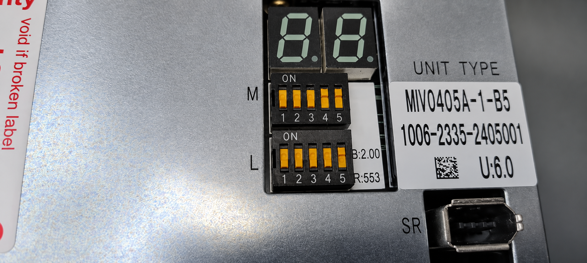
| Nameplate version | U:6.0 |
| Axes tested | 2 |
| Final result | Both axes: OK |
Function
The unit belongs to the Okuma MIV drive family. Both axes of this module were tested on the CNC in this case. The complete model designation and the installed version must be considered when identifying a replacement. MIV0405A-1-B5 is therefore retained exactly; the additional number 1006-2335 recorded in the order does not replace the complete type designation.
Assemblies and roles
| Area | Role / recorded work |
|---|
| Drive unit | Preventive overhaul |
| Power stage | Motor power conversion; no confirmed causal defect reported |
| Display | Status indication; final check OK |
| Cooling | Fan operation checked: OK |
| DIP switches | Original settings restored |
Incoming inspection and diagnosis
The Servo Drive Unit powered up during incoming inspection. It was then tested on the CNC. The recorded result was clear: the reported fault did not occur during this test and the unit ran without an alarm. This finding provided a basis for the next steps. However, it does not mean that the previously reported fault had not occurred at the customer’s machine. Differences in operating conditions can prevent a fault from being reproduced at the test station. The conditions responsible in this case were not conclusively established.
Preventive overhaul
After the initial CNC test revealed no fault, a standard overhaul was offered and approved by the customer. We cleaned the unit and performed a preventive overhaul. The work is recorded in the repair order. This sequence does not establish that a power-stage or power-supply defect causing the original alarm was repaired. The work in this case is therefore described as a preventive overhaul.
Troubleshooting and alarm information
The customer’s DC-bus note is not retrospectively converted into an alarm code supposedly observed on the unit. As general manufacturer information, the Okuma manual describes MIV alarm 03 as an out-of-range DC-bus voltage. This is troubleshooting guidance, not evidence that this particular code appeared during the workshop test. The following overview distinguishes the recorded observations from this manufacturer information.
Diagnostic overview
| Evidence | Message / finding | Meaning for this case |
|---|
| Customer note | MCS DC-bus voltage alarm | Reported fault; not reproduced in the initial CNC test |
| Workshop | Initial CNC test without alarm | Original cause remains unconfirmed |
| Manufacturer reference | 03: Inverter DC bus voltage error | DC-bus voltage outside range; check supply and MIV/MPS/MPR system |
| Final check | Both axes: OK | Documented result after overhaul |
Final CNC test
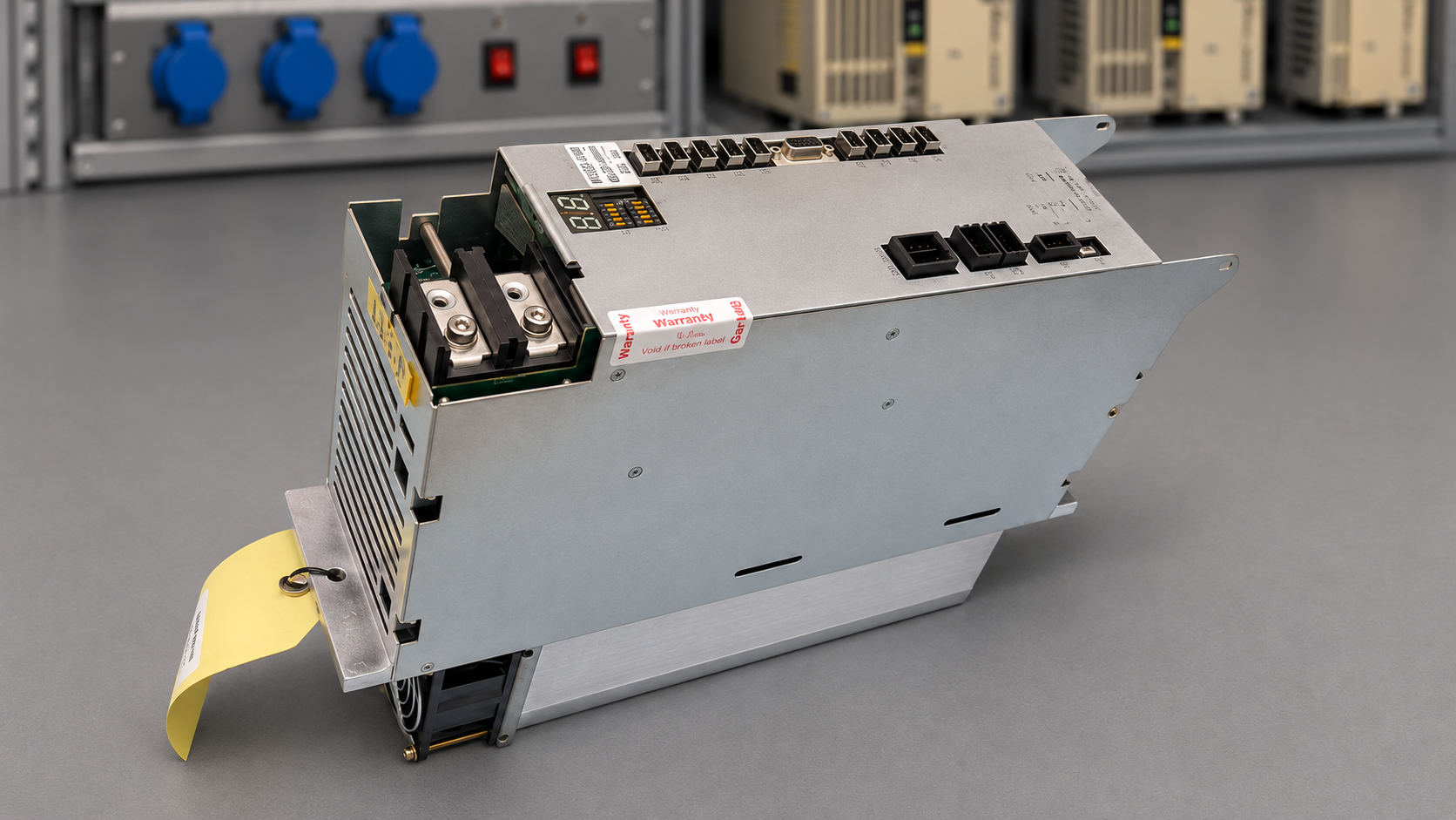
The unit was tested on the CNC again after overhaul. Both axes were tested and recorded as OK. The display and fan operation were also recorded as satisfactory. The DIP switches were restored to their original settings. This provides a documented final assessment of the overhauled unit. No specific test duration, load or speed is inferred from these entries. The original video shows the test setup and test run.
Prevention and information for recurring faults
Maintenance should include attention to airflow and cooling operation. If a fault occurs again, a photo of the complete alarm screen, the drive-module displays and a description of the operating state will help. In particular, record whether the message appears at power-up, when the axes are enabled or during movement. These details allow a comparison between machine conditions and workshop testing. Electrical checks should be carried out by qualified personnel, following the safety and discharge instructions in the documentation applicable to the machine.
What this case shows for maintenance
A reported machine fault and a workshop test without an alarm are not mutually exclusive. The important step is to document both observations and use them to determine what to do next. For this order, cleaning, preventive overhaul and the final test of both axes are documented. These results do not yet establish whether the original fault remained absent after reinstallation. This case report is not based on a customer confirmation following reinstallation.
Sources
Workshop documentation: project 123542, repair order 107204-1; incoming and outgoing photographs, test video and repair entries dated April and July 2026.
Okuma DRIVE UNIT MCS / MCSII Maintenance Manual, 4184-E-R6, 7th Edition, April 2005 (MIV0405A-1 PU: p. 6; alarm 03: p. 30).
Test video
Photos before and after overhaul
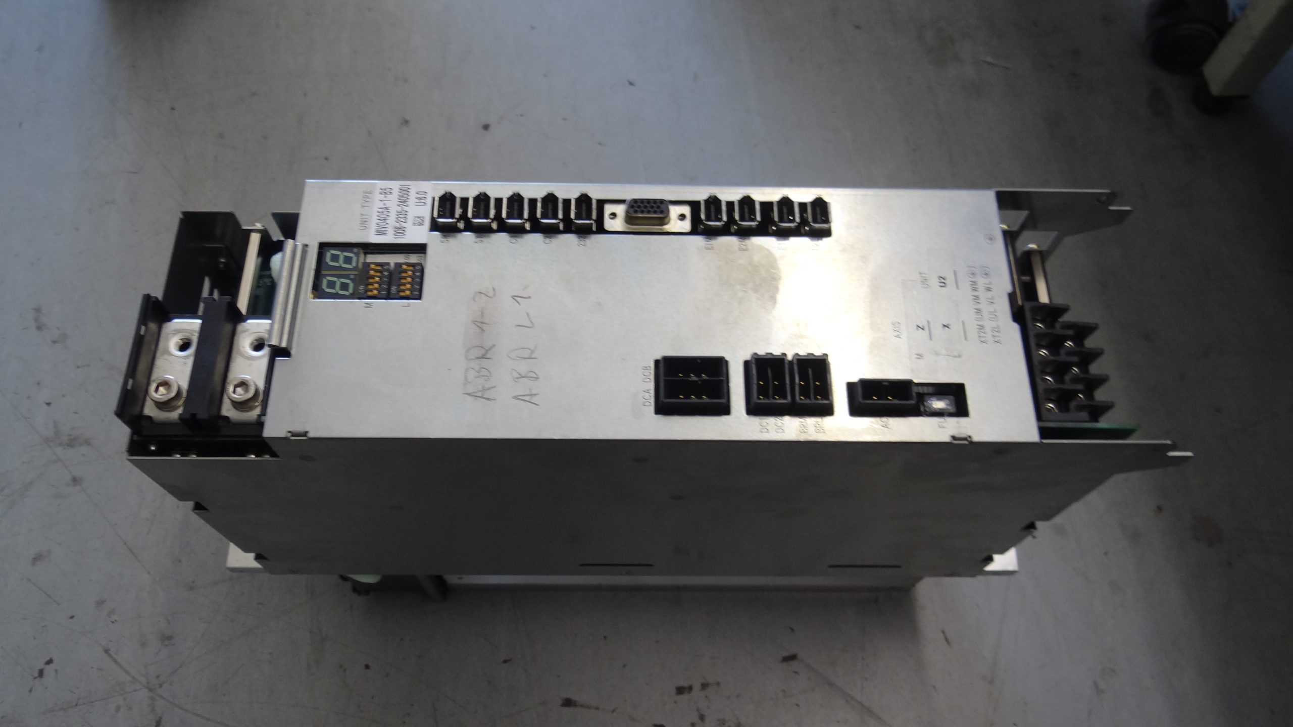 Incoming condition
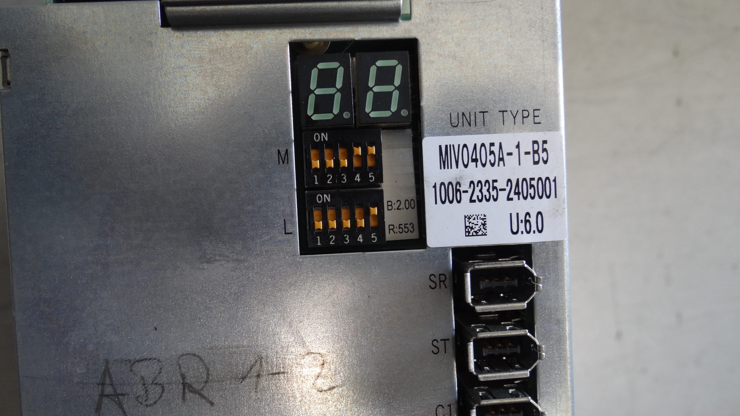 Incoming condition – nameplate
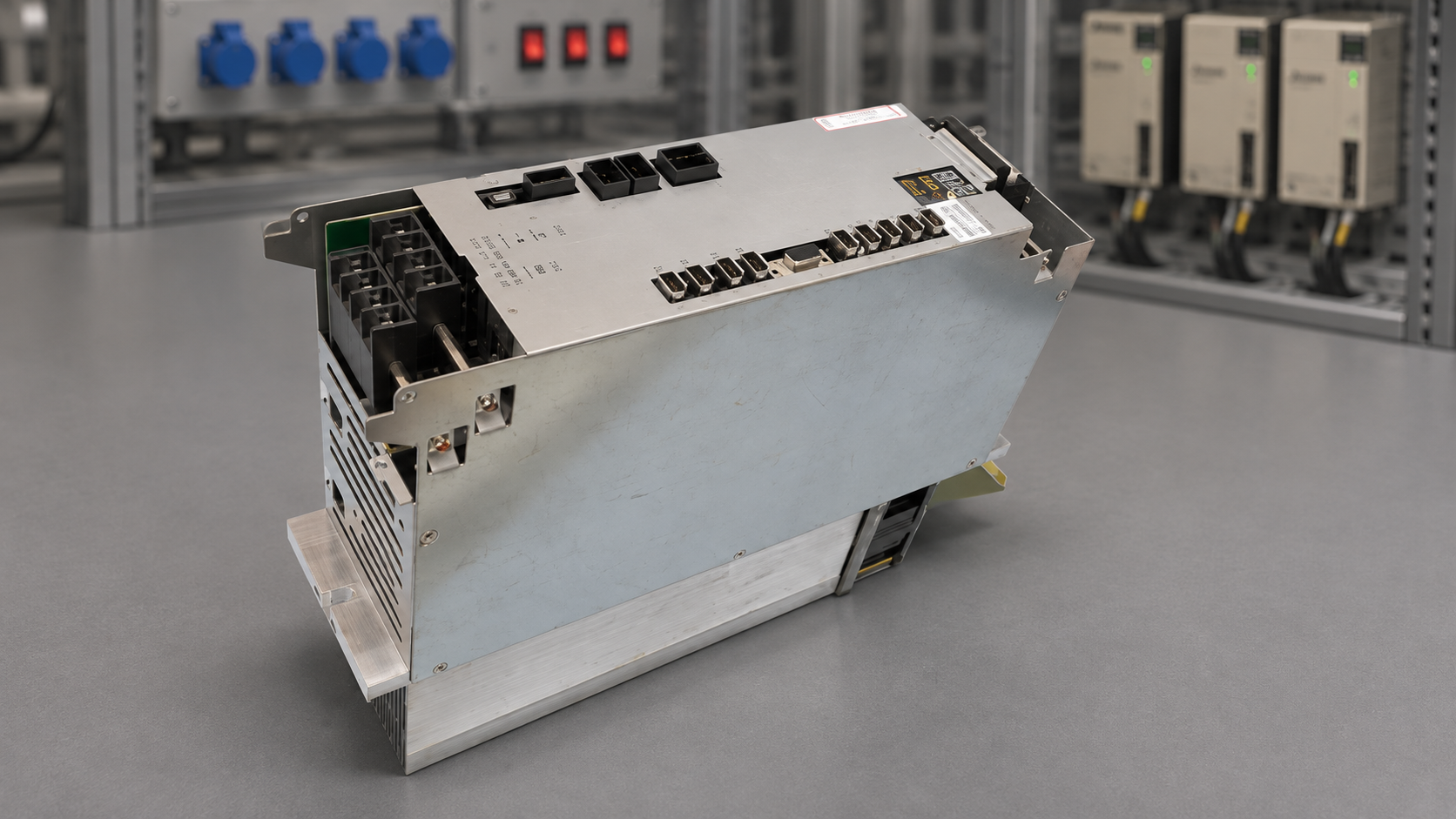 After overhaul
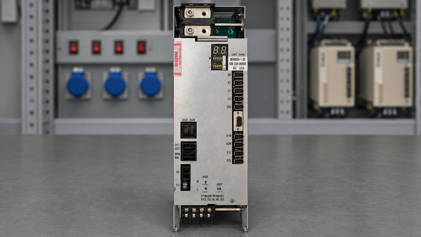 After overhaul
 After overhaul – nameplate
 After overhaul
Repair price and turnaround time
Current information and a repair enquiry are available on the product page linked below. The actual scope and turnaround time are agreed after assessment of the unit. The dates of this workshop case do not constitute a lead-time commitment for a new order.
Product page and repair enquiry
Repair enquiry
Do you need an inspection or overhaul of your Okuma MIV0405A-1-B5? Send us the complete type designation, a nameplate photograph and the fault description. You can request a quotation through the product page. View the matching product
Technical service: application and system integration
MIV0405A-1 is a two-axis BL servo drive in the Okuma MCS system. MPS/MPR supply the DC bus; servo, encoder and converter links connect control, feedback and supply. The inverter regulates the motors. This order does not identify the machine model.
For replacement enquiries, provide the machine model, controller version, complete drive nameplate and both motor nameplates. Matching connectors or similar housings do not establish interchangeability. Retain the complete designation MIV0405A-1-B5, including its suffix. We do not provide an unverified list of compatible machines.
A servo drive works in a closed control loop: the controller requests a movement, the feedback system reports the actual movement, and the drive adjusts motor actuation according to the difference. Electrical energy becomes controlled mechanical axis motion. In CNC machinery, this can serve feed or positioning tasks; the actual axis assignment depends on the machine configuration. A fault may therefore only become apparent when control, power supply, wiring, feedback and mechanics operate together. This explains the general control principle and does not establish the cause of this case.
Alarm list: selected MIV messages
General manufacturer information, not additional findings from this repair. Record the alarm number together with its complete additional code. This selection does not replace the machine-specific manual.
| MIV alarm | Meaning |
|---|
| 01 | Supply-unit fault |
| 02 | Converter-link fault |
| 03 | DC-bus voltage outside limits |
| 04 | Excessive motor current |
| 05 | Inverter overheating |
| 06 | Inverter overload |
| 07 | AC input voltage outside limits |
| 10 | Encoder communication fault |
Okuma manufacturer manual 4184-E-R6, 7th edition: system p. 1, two-axis configuration pp. 5–6, motor selection pp. 11–13, alarms pp. 29–31. References use printed page numbers. Do not equate MIV, MPS/MPR and exception codes.
Troubleshooting: preparing an effective workshop diagnosis
The following is our practical recommendation for collecting diagnostic information. It does not describe checks already performed on your machine or identify a failed component.
| Observation | Information to record | Diagnostic value |
|---|
| Fault at power-up | Photograph the alarm screen, visible module displays and message sequence. | Identifies which message appeared first. |
| Fault when enabling an axis | Note the affected axis and last fault-free operating state. | Distinguishes power-up from enabling as the trigger. |
| Fault during movement or machining | Record the program step, direction of movement and workpiece situation. | Supports a targeted test request. |
| Fault after extended operation | Note time since startup and differences from the cold machine. | Makes intermittent behaviour easier to compare. |
| Several axes affected together | Record all affected axes and simultaneous messages. | Avoids narrowing the investigation to one module too early. |
| Workshop test without a fault | Compare machine observations with the workshop record and identify differences. | A fault-free test alone does not explain the original incident. |
| Fault after reinstallation | Record the date, whether the message is identical, and any intervening work. | Helps distinguish recurrence from a different fault. |
Do not experiment with module swaps, motor wiring or parameters without a qualified technician and the correct machine documentation. Electrical work requires safe isolation, discharge and verification that hazardous voltage is absent. For an initial enquiry, photographs and a clear description of the fault are sufficient.