17.09.2026 by Viktor Siebert
Okuma MIV03-1-B1 or 1006-2213 Servo Drive Unit with Alarm 03: Repair of a Servo Drive Unit with a DC Bus Voltage Fault
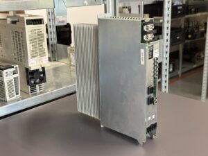
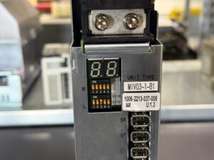
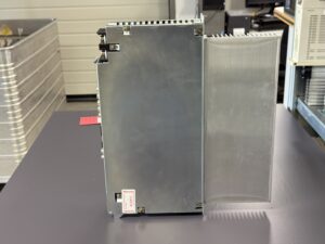
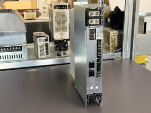
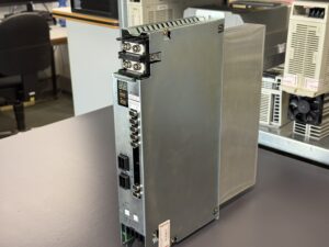
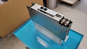
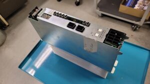
The Okuma MIV03-1-B1, order number 1006-2213, is a single-axis servo drive unit for BL and PREX servo motors. The module is used in older Okuma CNC machines and is designed for a motor output of up to 3 kW.
The servo drive unit was sent to us with Alarm 03. According to the Okuma manual, this alarm means:
“Inverter DC bus voltage error”
The voltage in the inverter’s DC bus is outside the permitted range. Either an excessively high or an excessively low DC bus voltage may have been detected.
This fault should not be regarded solely as a problem with the external power supply. In addition to the incoming supply voltage and the upstream Okuma power supply unit, faults inside the MIV03-1-B1 may also cause Alarm 03.
Meaning of Alarm 03
Okuma MIV units indicate different types of faults on the seven-segment display. In the event of a regular alarm, “AL” and the corresponding alarm number are displayed alternately. With a single-axis MIV03-1-B1, it is therefore important to determine whether “AL” and “03” are actually displayed.
According to the Okuma documentation, Alarm 03 indicates that the inverter DC bus voltage is too high or too low.
The module continuously monitors the DC bus. This DC voltage is generated by the upstream MPS or MPR power supply unit and transferred to the MIV unit through the DC bus connection. If the measured voltage leaves the permitted range, the drive is switched off to protect the power electronics and the connected motor.
Two values are stored in the fault data:
- XXXX represents the detected overvoltage value.
- YYYY represents the detected undervoltage value.
In MCS systems, the hexadecimal value 7FE0 corresponds to a voltage of 500 V. In MCS II systems, the same value corresponds to 550 V.
This additional data can assist with diagnosis. The visible alarm number alone initially indicates only that the DC bus monitoring circuit has detected an impermissible voltage.
Possible Causes of the Fault
Alarm 03 can be triggered by various faults within the complete DC bus system. It is therefore necessary to consider not only the servo drive unit but also the surrounding system.
Possible causes include:
- Unstable or missing incoming power supply
- Phase loss or severe voltage fluctuations
- Fault in the upstream Okuma MPS or MPR unit
- Faulty DC bus connection
- Aged capacitors
- Faulty voltage measurement inside the MIV unit
- Problems with the internal power supply
- Thermally or electrically damaged components
- Contact problems at connectors and circuit boards
- Interrupted connections or increased contact resistance
- Overvoltage during motor deceleration
- Faults in the regeneration or braking energy circuit
In older Okuma drive systems in particular, components can change their electrical characteristics after many years of operation. A module may initially function when cold and fail only after warming up, during acceleration or under increased load.
Incoming Inspection of the Okuma MIV03-1-B1
At the beginning of the repair process, the servo drive unit was clearly identified. The designation MIV03-1-B1 describes a single-axis MIV unit for BL or PREX motors. The corresponding inverter power unit has order number 1006-2213 and, according to the Okuma documentation, is designed for a motor output of 3 kW or 4 hp.
The unit was then inspected externally and internally. During this inspection, we pay particular attention to:
- Contamination and deposits
- Thermally discoloured areas
- Damaged or aged capacitors
- Suspicious power semiconductors
- Interrupted PCB tracks
- Poor solder joints
- Damaged connector contacts
- Condition of the cooling system
- Signs of previous repairs
- Abnormalities in the voltage measurement circuit
However, a visual inspection alone is not sufficient for Alarm 03. Components that appear normal externally can still produce incorrect readings when voltage is applied, after warming up or under load.
Inspection of the Power Supply and DC Bus
With this type of fault, it is first necessary to determine whether the actual DC bus voltage is incorrect or whether the MIV03-1-B1 is measuring the voltage incorrectly.
For this purpose, the relevant power supply sections and measuring circuits are checked. The diagnosis includes:
- Inspection of the DC bus supply
- Testing the internal supply voltages
- Measuring the capacitors
- Checking the voltage measurement circuit
- Checking signal transmission to the control system
- Testing the power semiconductors
- Checking for short circuits or unintended leakage currents
- Thermal examination of suspicious components
- Assessment of the circuit boards and connectors
If the DC bus has a stable voltage while the electronics continue to generate Alarm 03, the internal voltage measurement or signal processing circuit may be faulty. If the actual DC voltage is already fluctuating, the upstream power supply and the DC bus connection must also be investigated.
For this reason, the Okuma manual recommends not only replacing the MIV unit but also checking the incoming voltage and the MPS or MPR power supply unit.
Repair of the Servo Drive Unit
Following the fault analysis, the affected areas were repaired. Faulty components were not assessed solely by their external appearance but were also tested electrically. Components showing electrical or thermal abnormalities were replaced.
Age-critical components in the relevant assemblies were also assessed. These include, in particular, capacitors and components in the internal power supply and DC bus monitoring circuits.
The unit was then thoroughly cleaned. Contamination can impair cooling, retain moisture and cause unwanted leakage currents over time. Oil mist, metal dust and other residues frequently enter the electrical cabinets of machine tools.
After the electrical work had been completed, solder joints, circuit boards, internal connections and connector contacts were inspected again. Only then was the functional test carried out.
Testing After Repair
A servo drive repair cannot be considered successful merely because no alarm appears immediately after the unit is switched on.
The Okuma MIV03-1-B1 must also operate reliably during acceleration, deceleration, direction changes and prolonged thermal loading. Alarm 03 may occur particularly during dynamic operating conditions because the DC bus voltage changes under these conditions.
The following points are therefore monitored during testing:
- Stable start-up of the module
- Fault-free communication with the drive system
- Stable internal supply voltages
- Behaviour of the DC bus
- Motor control at different speeds
- Acceleration and deceleration
- Motor current consumption
- Temperature development
- Behaviour during prolonged operation
- Any recurrence of Alarm 03
The repair is completed only when the module continues to operate reliably under realistic operating conditions.
Important: Alarm 03 or Exception Error 03?
In addition to regular Alarm 03, the Okuma manual also lists Exception Error 03. These two messages have different meanings.
- “AL” and “03” mean Inverter DC bus voltage error.
- “EL” and “03”, or a corresponding exception display, mean OPF error.
An OPF error indicates a fault in the option program file. Possible subcodes refer to the “OPF1” identification code, the “ED” end code, an incorrect checksum or an incorrect board name.
For a correct diagnosis, the complete display should always be documented. A photograph or video of the seven-segment display helps to prevent confusion.
Preventive Measures
Regular inspections are recommended to reduce unplanned downtime in older Okuma drive systems:
- Keep the electrical cabinet and ventilation paths clean
- Check fans and filter mats
- Check connectors for secure seating
- Inspect the DC bus connections
- Pay attention to unusual smells or discolouration
- Document the alarm history
- Investigate recurring voltage fluctuations
- Check older capacitors as part of preventive maintenance
- Do not repeatedly reset affected modules without diagnosis
- Record the complete alarm display and operating condition
If Alarm 03 occurs mainly during acceleration, braking or after a specific operating period, this information should be included in the repair request. Such details make it easier to reproduce the fault under test conditions.
Conclusion
Alarm 03 on an Okuma MIV03-1-B1 indicates that the DC bus voltage is either too high or too low. The cause may be located in the servo drive unit, the upstream power supply, the incoming supply voltage or the DC bus connection.
A reliable repair therefore requires more than a simple functional test. The actual DC bus voltage, the internal voltage measurement circuit and the power electronics must be checked, followed by testing under dynamic and thermal load.
After repair and successful final testing, the Okuma servo drive unit can be returned to service in the machine.
Price, Lead Time and Further Information
Current information on the price and lead time of the Okuma MIV03-1-B1 or 1006-2213 Servo Drive Unit can be found on the corresponding product page.
Further information about our repair services for Okuma servo drives, spindle drives and spindle motors is available in our Okuma service section.
📞 Please feel free to contact us if you have any questions about your Okuma drive technology or a specific fault. Our experienced team will be pleased to assist you with the technical assessment, repair and testing of your unit.
Okuma MIV03-1-B1 / 1006-2213
Technical Specifications
| Feature | Technical information |
|---|
| Manufacturer | Okuma |
| Model | MIV03-1-B1 |
| Assembly type | MIV servo drive unit / inverter unit |
| Order number | 1006-2213 |
| Version | Single-axis inverter unit |
| Motor type | Okuma BL or PREX servo motor |
| Motor output | 3 kW |
| Motor output in hp | 4 hp |
| Control environment | Okuma MCS or MCS II |
| Status indication | Seven-segment display via MFP1 Card |
| Reported fault | Alarm 03 |
| Alarm designation | Inverter DC bus voltage error |
| Meaning | DC bus voltage too high or too low |
| Cooling | Heat sink, combined with electrical cabinet ventilation depending on the system |
| Manual reference | Okuma MIV Unit, Section 1, Inverter Unit |
| Production year | Cannot be clearly determined from the available documentation |
| Weight and dimensions | Not specified in the available documentation |
Application Environment and Compatible Equipment
The Okuma MIV03-1-B1 is a single-axis inverter unit used in Okuma CNC machines with MCS or MCS II drive systems. According to the available Okuma documentation, it is intended for controlling BL and PREX servo motors with a motor output of up to 3 kW or 4 hp.
The complete MIV unit consists of a control board, the MFP1 display card and the inverter power unit. The exact control board version depends on the motor type and the configuration of the machine.
When replacing an MIV unit, the exact type, control board version, motor configuration and machine parameters must be considered. A mechanically similar MIV module is not automatically compatible with every Okuma machine.
Functional Description
The Okuma MIV03-1-B1 supplies and controls an Okuma BL or PREX servo motor. The DC voltage provided by the upstream MPS or MPR power supply unit is converted by the power electronics into a regulated motor output.
The assembly processes commands from the CNC control, evaluates the motor feedback and regulates motor current, speed and position. At the same time, it monitors the DC bus, motor currents, inverter temperature, encoder communication and the connection to the Okuma control system.
If one of the monitored values leaves the permitted range, the MIV unit disables the motor output and generates an alarm to protect the power electronics, motor and machine.
Components
The Okuma MIV03-1-B1 consists of several coordinated assemblies. The ICB1F control board processes the control, regulation and monitoring signals. The IVPB03 power board controls the relevant functions of the power electronics. The E4809-045-209A connection board electrically connects the individual assemblies. The MIV0303 power section converts the DC bus voltage into the regulated output required by the connected servo motor.
| Name | Designation on the PCB | Quantity | Function |
|---|
| Control board | ICB1F, 1-Axis | 1 | Processing of control, regulation and monitoring signals |
| Power board | IVPB03 | 1 | Control and monitoring of the power electronics |
| Connection board | E4809-045-209A | 1 | Electrical connection between the internal assemblies |
| Power section | MIV0303 | 1 | Regulated power supply for the connected servo motor |
Alarm Messages and Troubleshooting
| Code | Fault description | Possible cause | Inspection and corrective action |
|---|
| 01 | Power Supply Unit Error | Fault in the MPS/MPR unit, incoming supply or control voltage | Check the incoming voltage, operating conditions and error data of the power supply unit |
| 02 | Converter Link Error | Communication fault or timeout involving the power supply unit | Check the converter link cable, MIV unit and MPS/MPR unit |
| 03 | Inverter DC Bus Voltage Error | DC bus voltage too high or too low | Check the incoming supply, DC bus, MIV unit and MPS/MPR unit |
| 04 | Motor Power Line Overcurrent | Overcurrent in the motor power circuit | Check the motor, motor cable and MIV power section |
| 05 | Inverter Overheat | Temperature of the inverter unit is excessively high | Check cooling, operating environment, contamination and MIV unit |
| 06 | Inverter Overload | Load exceeds the inverter protection curve | Reduce the machining load and check the servo data file and MIV unit |
| 07 | Commercial Power Source Error | Incoming voltage too high or too low | Check the supply voltage, cable cross-section and cable length |
| 09 | Motor Winding Changeover Error | Fault during motor winding changeover | Check the changeover contactors and servo data file |
| 10 | Encoder Communication Error | Communication error involving the position feedback system | Check the encoder, encoder cable and MIV unit |
| 11 | Encoder Error | Encoder cannot correctly detect the position data | Check or replace the motor-mounted encoder |
| 12 | Encoder Initialization Error | Motor encoder initialization failed | Check the encoder, encoder link cable and MIV unit |
| 20 | Motor Overheat | Motor or encoder temperature is too high | Check the operating load, motor, encoder and wiring |
| 21 | Servo Link Communication Error | Commands from the NC control cannot be received | Check the servo link cable, FCP board and MIV unit |
| 22 | Servo Link Cable Breakage | Interruption in the servo link connection | Check the cable path, connectors, FCP board and MIV unit |
| 24 | Servo Data Error | Servo data cannot be processed | Check the servo data file and NC software |
| 28 | DIFF Over | Position error is excessively large | Check the mechanical system, motor, MIV unit and control settings |
Alarm 03 Diagnostic Information
Alarm 03 is generated when the DC bus voltage of the inverter unit rises above or falls below the permitted range.
The stored fault information is structured as follows:
- XXXX: detected overvoltage value
- YYYY: detected undervoltage value
For MCS systems, 7FE0 hex corresponds to 500 V.
For MCS II systems, 7FE0 hex corresponds to 550 V.
According to the Okuma documentation, the following areas should be checked:
- Incoming supply voltage
- Upstream MPS or MPR power supply unit
- DC bus connections
- Internal voltage measurement circuit
- MIV inverter unit
Important Distinction Between Alarm and Exception Error
The display type must be considered when diagnosing fault number 03:
| Display | Meaning |
|---|
| AL 03 | Inverter DC bus voltage error |
| Exception Error 03 | OPF error in the option program file |
Exception Error 03 can refer to an incorrect “OPF1” ID code, an incorrect “ED” end code, a checksum error or a board name error. It is therefore important to record the complete sequence shown on the seven-segment display.