31.03.2026 by Viktor Siebert
Okuma Servo Drive Unit MIV0102A-1-B5 (1006-2325) with Alarm 03 Inverter DC bus voltage error and Alarm 05 Inverter overheat caused by cooling problem and worn power stage
Initial situation and fault pattern.
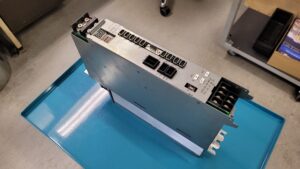
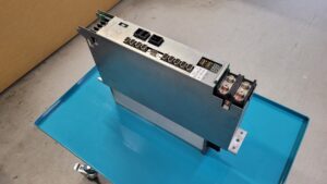
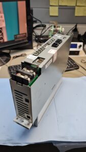
This repair case involved an Okuma Servo Drive Unit MIV0102A-1-B5 from the MIV series. The customer reported a periodically occurring Alarm 03 Inverter DC bus voltage error and additionally Alarm 05 Inverter overheat. What was noticeable was that the unit was not permanently dead, but the faults initially occurred only sporadically. This exact behavior is critical in practice because the unit often continues to operate partially for a longer period and the actual damage is therefore often detected too late.
In our test machine, the behavior described by the customer could be reproduced. The alarms actually occurred under realistic operating conditions. According to the Okuma alarm table, Alarm 03 stands for an impermissible overvoltage or undervoltage of the inverter DC bus. Alarm 05 stands for excessive unit temperature in the inverter module. Neither of these are random messages. Technically, both match very well with a thermally overloaded power section with deteriorated cooling. The MIV unit documentation describes these two alarms exactly in that way.
Before opening the unit or unplugging connectors, always switch off the power, secure against reactivation, wait for the discharge time and verify absence of voltage. Measurements on live parts must only be carried out by a qualified electrician with suitable equipment and according to local rules.
Incoming inspection and initial diagnosis
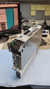
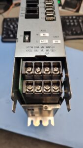
During incoming inspection, there was initially no mechanical total failure. The unit was externally complete, and connectors and terminals were visually unremarkable. For that reason, the decisive step was the functional test under load related conditions. It became apparent early on that the fan still started, but was hardly providing any effective airflow. After opening the unit, the cause was quickly visible. The fan was heavily clogged with dirt and mechanically rotated only with difficulty. This meant that the cooling reserve of the unit was practically gone.
At this point, it was already clear that Alarm 05 must not be evaluated as an isolated fan fault. If an inverter is operated for a long time with insufficient airflow, not only does the temperature rise. The entire power section also ages much faster at the same time. That is exactly why we did not limit the diagnosis to the fan, but evaluated the thermally stressed functional areas completely.
Technical analysis
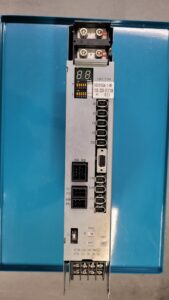
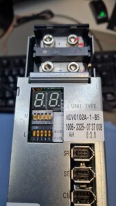
The MIV0102A-1-B5 is a digital AC servo drive for Okuma machine tools. The unit operates with a DC bus and from that supplies the inverter stage for the axes. According to the available device data, this is a 2 axis type designed for approx. 1.0 kW on the L axis and approx. 2.0 kW on the M axis. The power section is supplied by approx. 300 V DC, with the control section additionally supplied by 24 V DC. Typical operating conditions are stated as 0°C to 40°C and up to 80 percent humidity non condensing. The front 7 segment LED display is also used to output the alarm codes.
Technically, a clear cause and effect chain emerged here. The dirty and stiff fan reduced heat dissipation. As a result, the temperature in the inverter increased. Under this continuous thermal stress, the condition of the power stage deteriorated significantly. In this case, the highly stressed semiconductor sections and the aged electrolytic capacitors were already in a critical condition. This also explains why Alarm 03 and Alarm 05 could occur together.
Alarm 05 directly matches the excessive temperature increase in the inverter. Alarm 03 is often the secondary effect in such a case. If the power section operates unstably under thermal stress, the DC bus voltage can no longer be processed cleanly. In that case, the external supply does not necessarily have to be poor. Internal weakness in the power stage can also cause the DC bus monitoring to reach its limit. This is exactly the point where a simple fan replacement is no longer sufficient. The cooling was the trigger, but no longer the only damage.
It is also noticeable and very typical in practice that such units often still start, reference or run in partial load operation for some time. Under longer load periods or at higher ambient temperatures, the system then tips over into overtemperature or DC bus errors. This explains why customers often first perceive such damage as an intermittent fault.
Repair measures and overhaul
During the repair process, the unit was completely opened, cleaned and technically evaluated. The dirty fan was not viewed merely as an isolated cause, but as an indication of already advanced thermal pre damage throughout the entire power section.
The repair therefore included thorough cleaning of the airflow path and cooling surfaces, replacement of the worn cooling components and the overhaul of the thermally and electrically stressed functional areas in the power section. In addition, aged storage and smoothing functional assemblies of the power supply section were replaced because their condition was already critical and continued operation without overhaul would very likely have led to renewed failure. The affected power areas were electrically and thermally reassessed after the repair.
In this case, the important decision was against a minimal repair. A pure fan replacement would have restored airflow in the short term, but would not have stabilized the already weakened power stage. That would have meant a high probability of failure remaining. That is exactly why this unit was repaired functionally and not only symptom oriented.
As a preventive measure for such units, timely fan replacement is crucial. If the cooling is renewed before reaching the mechanical end of life and the control cabinet environment remains clean, many of these overtemperature and secondary damage cases can be avoided.
Final functional test
After the repair, the unit was tested in the test machine under realistic conditions. The test covered power on and off behavior, stable enable, behavior under low load and the thermal behavior over the test duration. In addition, the restart behavior after repeated cycles was observed because that is exactly where unstable power stages often become noticeable again.
After the repair, the unit ran without a renewed occurrence of Alarm 03 and Alarm 05. The temperature behavior remained stable, the output stage operated reproducibly in the test and without thermally caused shutdowns. Even after repeated power cycling and extended running time, no abnormalities appeared.
Conclusion
The actual trigger was a heavily contaminated and stiff fan. The decisive technical damage, however, was deeper. Due to permanently insufficient cooling, the power stage had already aged to such an extent that Alarm 03 and Alarm 05 became understandable and reproducible under real operating conditions. In such a case, a fan replacement alone is no longer enough.
After cleaning, overhaul of the stressed power areas and renewal of the affected cooling and supply functions, the unit could be tested stably again. The repair is sustainable mainly because not only the visible trigger was eliminated, but also the already damaged functional areas were repaired as well.
For more information about our Okuma repairs, please click here.
📞 Feel free to contact us if you have any questions regarding your Okuma drive technology. Our experienced team is always ready to provide you with expert advice and support.
Technical specifications
| Field | Value |
|---|
| Manufacturer | Okuma |
| Device type | Digital AC servo drive / inverter unit |
| Model designation | MIV0102A-1-B5 |
| Series | MIV |
| Power | L axis approx. 1.0 kW, M axis approx. 2.0 kW |
| Input voltage | approx. 300 V DC power section, 24 V DC control section |
| Output voltage | Internal DC bus, motor side inverter dependent |
| Rated current | not clearly specified in the available alarm document, device dependent |
| Control type | Digital AC servo drive |
| Feedback | Encoder Link, suitable for Okuma BL servo motors |
| Cooling | Forced cooling with fan |
| Protection rating | approx. control cabinet device, exact protection rating not specified in the available document |
| Ambient temperature | 0°C to 40°C |
| Mounting | Control cabinet mounting |
| Origin | Okuma CNC machine tools |
| Product status | older series, today often only available in existing machines or on the spare parts market |
Operating environment and possible applications
The MIV0102A-1-B5 was typically used in Okuma CNC machine tools. Due to its two axis design, such units are often found in axis drives of machining centers, lathes and comparable machine concepts.
Typical years of use are more in the area of older installed machine stock. In practice, such units are mainly relevant today in systems where the original technology continues to be operated and replacement procurement is only possible to a limited extent.
Typical applications are axis movements with high repeat accuracy, position control and controlled acceleration within the Okuma system environment. Requirements for the environment and control cabinet are clean airflow, functioning fans, unobstructed cooling paths, stable power supply and limited ambient temperature. Dust, oil mist, clogged air channels and long periods of thermal continuous load are critical.
Functional description
The basic function of the unit is the conversion of the provided DC bus voltage into a controlled motor current for the connected axes. The power stage, control system and feedback work closely together.
The power section handles the energy conversion. The control system processes setpoints and monitors internal states. The feedback system returns motor position and movement information to the control. Via Servo Link, Encoder Link and Converter Link, the unit is integrated into the Okuma system.
The axis enable is only released when the internal states are plausible. Protective logics monitor, among other things, DC bus voltage, temperature, overcurrent, communication states and feedback. Thermal monitoring is safety relevant because a thermally overloaded power stage can quickly trigger secondary damage. Signal monitoring is equally safety relevant because feedback or communication faults directly affect axis control.
Alarm messages and troubleshooting
| Alarm code | Description | Possible cause | Recommended action |
|---|
| 01 | Power supply unit error | Fault in supply module, voltage problem, regeneration or status fault | Check source voltage, check operating conditions, check MPS/MPR |
| 02 | Converter link error | Communication fault or timeout in Converter Link | Check Converter Link cable, check MIV, check MPS/MPR |
| 03 | Inverter DC bus voltage error | DC bus voltage too high or too low | Check source voltage, check MIV, check MPS/MPR |
| 04 | Motor power line over current | Overcurrent in motor line | Check motor, check MIV |
| 05 | Inverter overheat | Inverter temperature too high | Check operating conditions and cooling, check MIV |
| 06 | Inverter overload | Electronic overload in inverter | Reduce load, check operating conditions, check servo data file, check MIV |
| 07 | Commercial power source error | Input voltage faulty | Check mains voltage, check power cable, check MPS/MPR |
| 09 | Motor winding changeover error | Error during winding changeover | Check changeover magnet or changeover function |
| 10 | Encoder communication error | Communication fault over Encoder Link | Check axis encoder, check encoder cable, check MIV |
| 11 | Encoder error | Motor encoder does not supply valid position data | Check or replace motor encoder |
| 12 | Encoder initialization error | Error during motor encoder initialization | Check encoder, encoder cable and MIV |
| 17 | Magnetic encoder error | Magnetic encoder fault or mismatch with servo data file | Check servo data file, check magnetic encoder and cable |
| 18 | Resolver error | Resolver fault or interruption | Check resolver and resolver cable |
| 20 | Motor overheat | Motor temperature too high | Check operating conditions, motor, encoder and encoder cable |
| 21 | Servo link communication error | Fault in Servo Link to NC | Check Servo Link cable, MIV and FCP board |
| 24 | Servo data error | Transferred servo data cannot be processed | Check servo data file and NC software |
| 25 | Command error | Positioning or mode data faulty | Check servo data file and NC software |
| 38 | Motor overload | Electronic motor overload | Check operating conditions, reduce load, check servo data file |
| 40 | Tandem control communication error | Communication fault in tandem control | Check MIV and Servo Link |
The alarm codes and meanings above are taken from the alarm table of the Okuma MIV unit.
Assembly overview
| Assembly | Functional designation | Function | Notes for inspection or repair |
|---|
| Control board | ICB1H or E4809-770-138 | Processes control, monitoring, communication and internal enables of the MIV drive | Visual inspection for thermal stress, connectors, solder joints and supply states. In fault patterns with unstable control or communication problems, inspect specifically |
| Power board | IVPB0102A-1-B5 | Controls and distributes the power signals between control section and power stage | Check for thermal stress, contact problems, aged assemblies and reliable signal transfer to the power stage |
| Connection board | E4809-045-209A | Internal electrical and mechanical connection between the functional assemblies | Check for connector condition, conductor path damage, transition resistance and secure fit |
| Connection board | E4809-045-209A | Second identical connection assembly inside the unit | Same inspection as for the first connection board, with particular focus on contact stability and thermal traces |
| Power stage | Power stage | Energy conversion for motor control, highly thermally and electrically stressed area | For Alarm 03 and 05 especially check for thermal pre damage, cooling condition, load traces and dropouts under load |