24.07.2026 by Viktor Siebert
Okuma MIV0102-1-B1 Servo Drive Unit Repair After Sporadic AL.03 Alarm
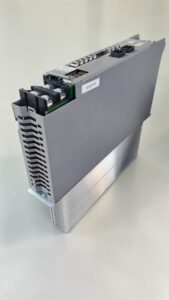
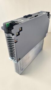
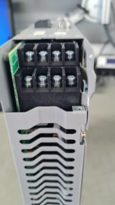
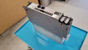
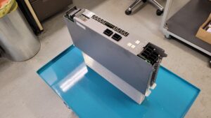
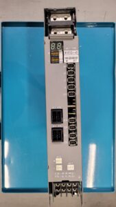
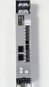
An Okuma MIV0102-1-B1 Servo Drive Unit was sent to our workshop with an unstable fault condition. During the initial inspection it became clear that alarm AL.03 appeared only sporadically. On the customer machine this resulted in irregular axis shutdowns and unexpected interruptions during machining operations.
After integrating the drive into our in-house test system, the fault could be reproduced reliably. The drive failed again after only a few motion cycles. The fault occurred independently of load changes and could be reproduced thermally.
According to the Okuma MIV alarm table, Alarm 03 stands for:
| Alarm | Description | Meaning |
|---|
| AL.03 | Inverter DC Bus Voltage Error | Inverter DC bus voltage outside allowable range |
The documentation describes this as an overvoltage or undervoltage condition inside the inverter DC bus. Okuma lists possible causes such as unstable input voltage, MPS/MPR power supply faults or internal defects inside the MIV power section.
Initial Diagnosis
During incoming inspection the following abnormalities were detected:
- thermally stressed power board IVPB0102A-1-B5
- aged DC bus capacitors
- increased ripple voltage inside the DC bus
- abnormal heat generation inside the power section
- unstable voltage supply under load
- sporadic fault triggering after axis movements
Additionally, the internal assembly structure was documented.
Components of the Okuma MIV0102-1-B1
| Assembly | PCB Designation | Quantity |
|---|
| Control board | ICB1H or E4809-770-138 | 1 |
| Power board | IVPB0102A-1-B5 | 1 |
| Connection board | E4809-045-209A | 2 |
| Power section | Power Unit | 1 |
The installed assemblies were identified directly from the inspected servo drive.
Failure Analysis
Further testing included:
- ESR measurement of all DC bus capacitors
- dynamic load simulation during axis movement
- thermal imaging of the power section
- gate driver verification
- DC bus voltage analysis under load
- internal power supply inspection
The following results were identified:
- unstable DC bus voltage under load transitions
- voltage drops during acceleration phases
- thermally damaged power components
- aged capacitors with elevated ESR values
- increasing instability inside the power stage
The failure matched the Okuma alarm definition for AL.03 “Inverter DC Bus Voltage Error” exactly.
Repair Process
The following work was performed:
- replacement of stressed DC bus capacitors
- replacement of thermally critical components
- rework of stressed solder joints
- cleaning of the power electronics
- thermal treatment of the power section
- dynamic load testing
- long-duration thermal stability testing
- verification of internal voltage stability
Special attention was focused on the IVPB0102A-1-B5 power board, where the root cause of the failure was located.
Final Testing
After the repair process, the Okuma MIV0102-1-B1 was tested again on our industrial test system.
The following procedures were completed:
- simulated axis motion
- dynamic load changes
- long-term runtime testing
- thermal stability testing
- DC bus voltage monitoring
- protection circuit verification
During the complete test procedure the AL.03 alarm did not reappear. The servo drive operated stably without any DC bus faults.
Customer Feedback
“The fault was previously unpredictable and occurred randomly. After the repair the axis is running stable and repeatable again.”
Preis und Lieferzeit für Okuma MIV0102-1-B1 Servo Drive Unit
Weitere Informationen zu unseren Okuma-Reparaturen finden Sie hier.
📞 Kontaktieren Sie uns gerne, wenn Sie Fragen zu Ihrer Mitsubishi-Antriebstechnik haben. Unser erfahrenes Team steht Ihnen jederzeit mit Rat und Tat zur Seite.
Technical Specifications Okuma MIV0102-1-B1
| Specification | Value |
|---|
| Manufacturer | Okuma |
| Model | MIV0102-1-B1 |
| Series | MIV Inverter Unit |
| Device Type | Digital AC Servo Drive / Inverter Unit |
| Configuration | 2-axis servo drive |
| Axis Power | L-axis approx. 1.0 kW / M-axis approx. 2.0 kW |
| Power Supply Section | approx. 300 V DC |
| Control Voltage | 24 V DC |
| Control System | Digital servo axis control |
| Communication System | Servo Link / Converter Link / Encoder Link |
| Encoder Systems | BL Servo Motor Encoder / Absolute Encoder / Magnetic Encoder |
| Cooling | Forced air cooling with fan |
| Mounting Type | Cabinet installation |
| Ambient Temperature | 0 °C to 40 °C |
| Humidity | up to 80 % non-condensing |
| Protection Functions | Overcurrent, Overvoltage, DC Bus Monitoring, Overheat, Encoder Monitoring |
| Fault Display | 7-segment LED display |
| Internal Assemblies | ICB1H control board, IVPB0102A-1-B5 power board |
| Machine Integration | Okuma CNC machines |
| Weight | approx. 5 kg to 11 lbs depending on configuration |
| Product Status | older Okuma MIV generation mainly used in repair and spare parts market |
| Manual Reference | Okuma MIV Maintenance Manual / MCS Motion Control System |
Operating Conditions
| Parameter | Description |
|---|
| Ambient Temperature | Industrial environment |
| Cooling | Proper cabinet ventilation required |
| Voltage Stability | Input fluctuations should be minimized |
| Vibration | Mechanical vibration should be minimized |
| Humidity | Non-condensing environment |
Integration with Other Equipment
The Okuma MIV0102-1-B1 is commonly used together with:
- Okuma CNC controls
- MPS/MPR power supply units
- Servo Link communication systems
- absolute encoders
- magnetic encoders
- servo axis motors
Functional Description
The Okuma MIV0102-1-B1 is a servo inverter unit designed for precise CNC axis control. The drive processes position and speed feedback signals from the encoder system and regulates motor current for the connected servo axes.
Integrated protection functions include:
- overcurrent protection
- DC bus monitoring
- thermal protection
- encoder communication monitoring
- Servo Link communication monitoring
- overload protection
The unit continuously supervises the stability of the DC bus voltage. Even small instabilities inside the intermediate circuit can trigger AL.03.
Important Alarm and Error Codes
| Alarm | Fault Name | Meaning | Action |
|---|
| AL.01 | Power supply unit error | Power supply fault | Check power supply |
| AL.02 | Converter link error | Converter communication fault | Check converter link cable |
| AL.03 | Inverter DC bus voltage error | DC bus voltage unstable | Check DC bus and power section |
| AL.04 | Motor power line over current | Motor overcurrent | Check motor and power section |
| AL.05 | Inverter overheat | Overtemperature | Check cooling system |
| AL.06 | Inverter overload | Overload condition | Check load and parameters |
| AL.10 | Encoder communication error | Encoder communication fault | Check encoder cable |
| AL.20 | Motor overheat | Motor overheating | Check motor |
| AL.21 | Servo link communication error | Servo Link fault | Check communication system |
| AL.32 | Speed deviation too large | Excessive speed deviation | Check mechanics and control |
The alarm codes are taken directly from the Okuma MIV alarm documentation.
Preventive Measures
To avoid similar failures we recommend:
- regular inspection of DC bus capacitors
- cleaning of cooling air channels
- thermal inspection of power modules
- verification of cabinet cooling
- input voltage monitoring
- visual inspection for thermal discoloration
- load analysis during dynamic axis movement
Conclusion
The sporadic AL.03 alarm on the Okuma MIV0102-1-B1 was caused by unstable DC bus voltage inside the power section. By repairing the power stage and performing extensive dynamic testing, the servo drive could be restored to stable operating condition.
The combination of thermal stress, aged capacitors and unstable voltage supply is one of the most common failure causes in older CNC servo drive generations of this type.