09.03.2026 by Viktor Siebert
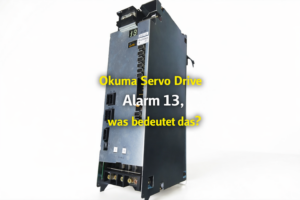
Okuma MIV06DB-1-B5: Error number 13 inverter bridge, power stage refurbished and preventive overhaul
Initial situation and fault picture.
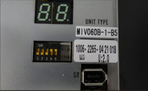
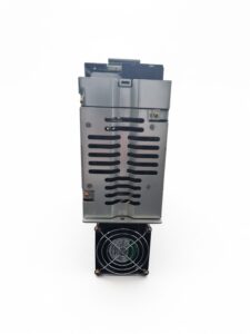
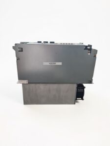
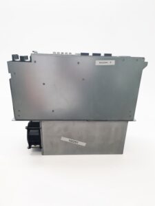
The Okuma Driver Unit MIV06DB-1-B5 (Okuma part number 1006-2265) came from a CNC system with error number 13, which was permanently active. The fault could neither be cleared by reset nor by switching on again. The affected axis therefore remained not enable ready.
The operator described the occurrence either directly after switching on or immediately when attempting axis enable. Technically noticeable was the lack of load dependence. A fault that is permanently present already at standstill often indicates internal self monitoring.
Okuma describes the status indication of the MIV unit via a 7 segment display, where for example an alarm is shown as “AL” plus number. For diagnosis it is therefore decisive whether an alarm number or an exception error number is present, because the number 13 has different meanings depending on the table.
Incoming inspection and first diagnosis
Before opening or unplugging connectors applies: switch off, secure against being switched on again, wait for discharge time, and verify absence of voltage. Measurements on live parts are carried out only by qualified electricians with suitable equipment and according to local rules.
During incoming inspection, the cooling path, plug connectors, and installation situation were checked, in particular contamination, restricted airflow, and thermal traces. After that, the fault was reproduced on the test setup. With a permanent fault picture, the focus was initially on the internal power conversion. In the de energized state, the power outputs were checked comparatively. The abnormality matched an internal fault in the area of the inverter bridge, not a pure feedback problem.
Technical analysis
The MIV06DB is an axis inverter within the Okuma MIV system. It generates a controlled, pulse width modulated three phase voltage for the servo motor from the DC link of the power supply and monitors DC link voltage, phase current, temperature, and the correct control of the power stage.
In the Okuma documentation, error number 13 in the exception error table is described as “Inverter bridge error”, thus as a fault of the power stage or the power section. In the present case, the occurrence already during start up and the electrical abnormality at the power outputs indicated the inverter bridge fault.
Such faults typically arise due to thermal overload, insufficient cooling in the control cabinet, or consequential damage after over current events, for example due to a damaged motor cable. The protective logic blocks the drive as soon as an impermissible condition is detected in the power section.
Repair measures and refurbishment
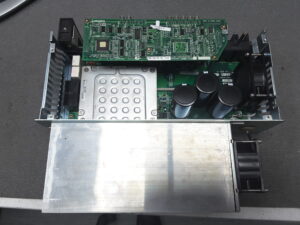
The device was preventively overhauled and the power stage was refurbished. Functional assemblies were processed, without naming individual components.
The following were carried out:
• refurbishment of the power section including restoration of insulation and heat dissipation
• checking and stabilization of the control and protective monitoring of the power stage
• cleaning of the cooling and plug area, check of air guidance and fan function
• contact check of the plug in connections in the power and control section
As preventive system notes were recorded:
• regularly check control cabinet temperature, filter mats, airflow, and fans
• visually check motor and motor cable, insulation measurements only by a qualified electrician
• professionally check supply quality and grounding
Final functional test
The functional test was carried out on the test bench with regulated supply. DC link voltage, output currents, and temperature were monitored. Tested were power on power off behavior, reference run at low speed as well as runs at medium and high speed, each with load changes within the permissible range.
The protective functions were monitored, in particular current, temperature, and signal monitoring. The result was stable and reproducible. Error number 13 did not occur again during test bench operation.
Conclusion
The permanently active error number 13 was classified as a fault in the area of the inverter bridge and thus the power stage. Through refurbishment of the power conversion and the preventive rework of cooling and contact points, the unit operates under defined thermal and electrical conditions. For a sustainable solution, checking the peripheral equipment in the system remains important, in particular motor cable, control cabinet climate, and supply quality.
Price and Delivery Time for Okuma Servo Drive Unit MIV06DB-1-B5 (Okuma 1006-2265
For more information about our Okuma repairs, please click here.
📞 Feel free to contact us if you have any questions regarding your Okuma drive technology. Our experienced team is always ready to provide you with expert advice and support.
Technical specifications
| Field | Value |
|---|
| Manufacturer | Okuma |
| Device type | Servo inverter unit (axis amplifier) |
| Model designation | MIV06DB-1-B5 (Okuma 1006-2265) |
| Series | MIV unit |
| Power | ca. 1.5 kW (axis and motor dependent) |
| Input voltage | DC link from power supply, ca. 300 to 560 V DC (system dependent) |
| Output voltage | three phase PWM, effective motor voltage depends on the DC link (ca.) |
| Rated current | ca. 6 A (axis dependent) |
| Control method | Digital servo controller, control via Okuma servo link |
| Feedback | Encoder link (motor mounted encoder), optional shaft encoder or absolute scale (system dependent) |
| Cooling | Forced air via heat sink in the control cabinet (ca.) |
| Protection class | ca. IP20 (control cabinet device) |
| Ambient temperature | ca. 0 to 45 °C, with sufficient airflow |
| Mounting | Plug in module, vertical in the drive cabinet (ca.) |
| Origin | unknown |
| Product status | unknown, often discontinued and in service environment (ca.) |
Operating environment and possible applications
Typical places of use are Okuma CNC machines such as lathes, machining centers, and milling machines, for feed axes and auxiliary axes. Typical years of manufacture, depending on machine and control, are ca. 1998 to 2008.
For stable operation, the following are important:
• clean, dry control cabinet without conductive dust and without coolant mist
• stable airflow with free cooling channels, functional fans, and clean filters
• EMC compliant wiring, shield terminations, and professional grounding
• thermal reserve with high cycle rates, strong accelerations, and frequent braking operation
Functional description
The basic function is conversion of the DC link voltage into a controlled three phase output voltage for the servo motor. The control unit processes setpoints from the controller, monitors the feedback, and drives the power stage. The power stage generates the PWM outputs and captures currents and states for the protective functions.
Enable and protective logic are safety relevant: In impermissible conditions, power output is blocked to avoid uncontrolled movement and consequential damage. Typical monitored values are DC link voltage, over current, and over temperature.
Alarm messages and troubleshooting
| Alarm code | Description | Possible cause | Recommended measure |
|---|
| 01 | Fault in the power supply unit | MPS/MPR power supply reports a fault, DC or AC supply outside tolerance | Check supply conditions, evaluate alarm data, check power supply and wiring |
| 02 | Converter link fault | Communication interruption or link cable defective | Check link cable and connectors, check environment for interference influences |
| 03 | DC link voltage too high or too low | Mains fluctuation, regeneration, loose supply | Check mains supply, check braking conditions, measurements only by a qualified electrician |
| 04 | Over current in the motor line | Short circuit, insulation fault, blocked mechanics | Check motor and motor cable, have insulation measured, check mechanics |
| 05 | Over temperature in the inverter | Fan failure, filter clogged, air path blocked | Ensure cooling air, check filters and fans, reduce control cabinet temperature |
| 06 | Overload (thermal model) | Continuous overload, incorrect parameterization, high inertia | Check load profile, check mechanics, plausibility check parameters |
| 07 | Mains fault | Under voltage, phase issue, supply interruption | Check mains quality, check connection and protective chain, measurements only by a qualified electrician |
| 10 | Encoder communication disturbed | Encoder link cable, contact issue, EMC disturbance | Check cable and shielding, clean and secure plug connections |
| 12 (Exception) | Gate signal fault | Control or protective monitoring detects an implausible signal | Do not continue operating the drive, proper professional check of the power stage |
| 13 (Exception) | Inverter bridge disturbed | Fault in the power section, consequential damage after over current or over temperature | Remove the drive, professionally refurbish and test the power stage |
| 14 (Exception) | Motor over current in the power section | Impermissible current flow in the power section, short circuit in peripheral equipment possible | Check motor, motor cable, and drive unit, check insulation and load |
| 20 | Motor over temperature | Motor overloaded, cooling insufficient | Reduce load, check motor cooling, find temperature cause in the process |
Assembly overview
| Assembly | Functional designation | Function | Notes for testing or repair |
|---|
| Control board (ICB1F 1-Axis) | Axis control and interfaces | Processing of setpoints, communication, monitoring | Visual inspection, plug contacts, supply rails, fault memory and status data |
| Power board (IVPB06DB) | Power control and protective monitoring | Driving of the power stage, capture of protective values | Check monitoring chains, thermal coupling, contact and plug area |
| Connection board (BTB71) | Internal connection and signal distribution | Connects control and power unit, distributes internal signals | Contact check, mechanical stress, correct seating in the plug in frame |
| Power section (MIV06DB) | Power conversion | Inverter bridge for the motor phases, PWM conversion | Check for electrical abnormalities, insulation, thermal stability |