09.04.2026 by Viktor Siebert
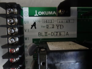
Repair of an Okuma BLII-D75A or BL2-D75A Order: 006-0613 Servo Drive Unit with Immediate OV and UV Indication After Power On
Initial Situation and Fault Pattern
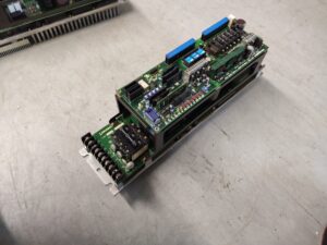
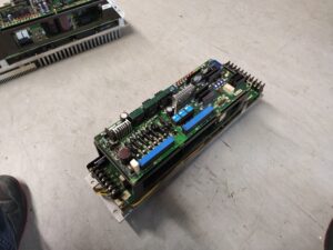
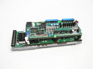
This repair case involved an Okuma AC servo drive of the BLII-D75A or BL2-D75A series with the associated power board E4809-770-069. The reported fault pattern was clear, but typically deceptive in the cause. Immediately after power on, the OV and UV LEDs lit up at once. So the drive did not first go into fault under load or during axis movement, but already at a very early stage during the startup of the power electronics. This exact behavior is technically conspicuous because overvoltage and undervoltage appear contradictory at first glance. If both indications are active simultaneously or directly one after the other, the cause is usually not the machine itself, but the internal structure of the power unit.
Incoming Inspection and Initial Diagnosis
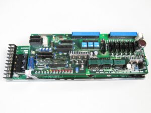
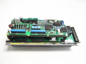
Already during the incoming inspection it became clear that the fault was not due to a simple disturbance in the DC link or a loose connection. The visual inspection revealed clear damage on the power board. In the area of the current carrying assemblies, thermal discoloration, damaged conductor paths and clear traces of consequential damage were visible. At the same time, the output stage itself was defective.
This is not an unusual picture on these Okuma power units when the assembly has been operated for a longer period with aged electrolytic capacitors. Especially on older units, the fault often begins inconspicuously. The drives may still run at first and perhaps only show occasional irregularities until one day OV and UV appear directly at power on. This exact point is important for diagnosis. The actual primary damage often does not lie in the output stage itself, but starts much earlier on the board.
Technical Analysis
The technical cause here was typical for aging power assemblies of this series. Capacitors inside the unit had aged and leaked. The electrolyte attacked conductor paths and adjacent functional areas. This leads to leakage currents, corrosion and, in the further course, also partial short circuits. At first, this destabilizes the signal paths on the power board. After that, the functional groups are damaged that shape clean drive signals for the power modules from the control signals. If this signal shaping no longer works cleanly, the actual transistor power stage is driven incorrectly or overloaded. At this point, the fault often ends in a hard failure of the power section.
The cause effect chain in this case was therefore clearly traceable. Aged and leaking capacitors led to conductive residues and damaged conductor paths. This resulted in faulty signal conditioning. After that, the power module was overloaded and destroyed. For the operator, the whole issue finally became visible only as an immediate OV and UV indication at power on.
That is exactly why the fault pattern often appears illogical. The unit shows voltage faults although the actual cause lies in the internal signal processing and in the condition of the board. Without opening and technical assessment, this connection often remains hidden.
Repair Measures and Overhaul
During the repair process, the unit was fully opened, cleaned and technically assessed. Damaged areas on the board were not only reworked superficially, but restored functionally or replaced if the damage was too severe. In this case the board was burned through and had to be replaced. In addition, the defective output stage was renewed.
The decisive point was not just to eliminate the obvious end damage, but to work through the entire cause chain. This included cleaning leaked residues, checking the stressed signal paths, reworking the load bearing areas and replacing the affected functional units. This is also where the preventive approach lies. If these units are overhauled in time, before conductor paths are attacked and signal stages are destroyed, a much greater consequential damage can often be avoided.
The case also had a second practical side. After the customer learned that the servo module could in principle still be saved, but that the board had already been damaged so severely that it had to be replaced, he had further power units from his machine overhauled as a precaution. From a technical point of view, this is understandable. Once one unit of this series shows the typical picture with leaking capacitors, it can be assumed that identical units with similar operating age may be in a comparable condition.
Final Functional Test
After the overhaul, the power unit was tested on the test bench with a controlled power supply. First, the on off behavior was checked. The decisive point was that no immediate OV or UV indication occurred anymore when switching on and that the power stage could initialize stably. After that, the control behavior was tested under low load and with several switching cycles. In addition, the signal conditions in the drive stage were monitored and the thermal development was checked.
In the further course, the unit was tested under medium and increased electrical load, as far as this could be sensibly and safely represented on the test bench. It was important here that the power stage enabled cleanly, the internal voltage states remained stable and no renewed irregularities occurred in the area of protective logic or signal conditioning. After the overhaul, the drive started up stably again and showed no renewed faulty behavior during the test.
Conclusion
The damage on this Okuma BLII-D75A or BL2-D75A was not an isolated output stage defect, but the result of longer term aging in the power board. The immediate lighting of OV and UV was only the final symptom of already advanced damage caused by leaking capacitors, damaged signal paths and, as a result, failure of the power stage. The repair is sustainable if not only the destroyed power section is replaced, but if the entire cause chain is technically processed. That is exactly why the preventive overhaul of such power units is in many cases much more economical than waiting until total failure. The described fault patterns and BLII fault indications are based on the Okuma troubleshooting documents for this series.
For more information about our Okuma repairs, please click here.
📞 Feel free to contact us if you have any questions regarding your Okuma drive technology. Our experienced team is always ready to provide you with expert advice and support.
Technical Specifications
| Field | Specification |
|---|
| Manufacturer | Okuma |
| Device type | AC servo drive / power unit |
| Model designation | BLII-D75A or BL2-D75A |
| Series | BLII-D / BL2-D |
| Power | approx. matching the 75 A performance class |
| Input voltage | 3 phase AC, permissible range according to troubleshooting approx. 170 to 242 VAC |
| Output voltage | PWM controlled 3 phase motor output, derived from the internal DC link, approx. input dependent |
| Rated current | 75 A |
| Control type | Transistorized power control with internal control and protective logic |
| Feedback | application dependent, Okuma servo system with motor feedback |
| Cooling | Heatsink, depending on installation condition cabinet supported |
| Protection class | Cabinet mounted device, no field side protection class |
| Ambient temperature | approx. 0 to 40 °C sensible operating range |
| Mounting | Control cabinet mounting |
| Origin | Japan |
| Product status | Legacy unit / installed base / no longer common in regular new series supply |
Operating Environment and Possible Applications
Typical machines
Okuma CNC lathes, machining centers and special purpose machines with BLII power axes
Typical years of manufacture
Mainly older installed machines, often from the 1980s and 1990s
Typical applications
Feed axes, positioning axes, servo electric machine movements in the machine tool sector
Requirements for environment and control cabinet
Clean cabinet air, stable mains supply, functioning heat dissipation, no conductive contamination, no moisture exposure, no oil containing condensation inside the unit
Notes on thermal and electrical load
High switching loads, capacitor aging, thermal cycling and long operating times favor failures. Heat accumulation, contaminated cooling surfaces and missing preventive overhaul are especially critical.
Functional Description
Basic function
The power unit converts the mains supply into a controlled drive for the servo motor. It provides the power for accelerating, regulating and holding the axis.
Interaction of power section, control and feedback
The control system specifies setpoints. The internal control processes this information together with the feedback from the motor or axis system. From this, drive signals for the power section are formed. The power section converts these signals into motor current.
Enable
The power section is only enabled after correct initialization and an internally stable voltage condition.
Protective logic
The unit monitors voltages, overcurrent conditions, regeneration, internal supply, overload and faults in the control board. In the event of implausibilities, the power enable is blocked.
Thermal monitoring
Heat development in the power section and the surrounding area is critical. Overheating can lead to malfunctions, drift and eventually consequential damage.
Signal monitoring
The internal signal conditioning is safety relevant. Faults in the drive of the power modules quickly lead to major secondary damage.
Why these functions are safety relevant
Faulty enabling or disturbed signal chains can cause uncontrolled current increases, destruction of the output stage or machine downtime. For this reason, such units must be professionally tested and repaired.
Alarm Messages and Troubleshooting
| Alarm code | Description | Possible cause | Recommended measure |
|---|
| PON off / LOSS on | Operating lamp does not light or LOSS active | Input supply too low or fuse defective | Check supply, check fuse, check connectors |
| OCM | OCM lamp lights up | Motor cable fault, motor insulation fault, connector issue, control or power unit fault | Check motor cable and insulation, check connectors, isolate assemblies |
| OCS | OCS lamp lights up | Control board or power unit fault, short circuit in motor cable, motor fault | Check motor cable, inspect control board and power unit according to manufacturer steps |
| OV | OV lamp lights up | Input voltage too high, loose power terminals, fault in regenerative circuit | Check supply, retighten terminals, inspect regenerative circuit |
| UV | UV lamp lights up | Input voltage too low, phase loss, power section or control board faulty | Check mains supply, phase status, terminals and power unit |
| BOH | BOH lamp lights up | Motor overload, connector problem, fault in control board or power unit | Check load, inspect connectors, isolate assemblies against each other |
| ROH | ROH lamp lights up | Regenerative IGBT fault, incorrect connector insertion, motor overload, resistor terminals loose | Check regenerative circuit, assess load, inspect connections |
| Circuit protector trips | Circuit protector trips | Wiring fault, short circuit in motor cable, IGBT or diode module defective | Check wiring, disconnect and test motor cable, inspect power section |
| Warning charge lamp remains on | Charge lamp does not go out after switch off | Fault in power unit | Wait discharge time and inspect or replace power unit |
| Motor hunts | Motor hunts or oscillates | IGBT fault, control board fault, fault in other connected units | Check power section, control board and connected assemblies |
| LOSS | LOSS lamp lights up | Control does not receive correct supply from the power unit | Check internal voltage supply, connectors and mains side |
Assembly Overview
| Assembly | Functional designation | Function | Notes for testing or repair |
|---|
| Power section | Output stage | Generates the controlled motor current | Check for short circuit, thermal damage and clean enable behavior |
| Power board | Okuma power board E4809-770-069 | Carries power and signal paths | Check for corrosion, damaged conductor paths and burn through |
| Signal conditioning | Drive stage for power modules | Shapes the control signals for the power stage | Always inspect together in case of unstable drive signals |
| DC link | Internal voltage preparation | Provides energy for the power level | Check for voltage stability and consequential damage |
| Protective logic | Monitoring and shutdown function | Detects voltage, current and regeneration faults | Always evaluate fault indications in relation to the primary cause |
| Mains connection area | Supply input and terminals | Supplies the unit | Check for loose terminals, transition resistance and phase faults |
| Regeneration branch | Braking and energy dissipation path | Limits DC link voltage | Must be inspected in case of OV and ROH |
| Heatsink area | Heat dissipation | Keeps power semiconductors within temperature range | Check for contamination and thermal discoloration |
| Connectors | Internal and external connection level | Connect control and power section | Check for contact problems and heat effects |
| Capacitor area | Aging relevant supply section | Filters and supports internal voltages | Inspect preventively and repair on older units |