19.04.2026 by Viktor Siebert
Repair of a Mitsubishi MDS-C1-SPHX-55 Spindle Drive Unit with Alarm 17 A/D Converter Error
Initial situation and fault pattern.
This repair case involved a Mitsubishi spindle drive unit MDS-C1-SPHX-55. The device arrived with alarm 17. In Mitsubishi documentation, alarm code 17 is described as an A/D converter error, meaning a fault in the current feedback or in the internal analog to digital acquisition of the drive. In the MDS-C1 documentation, alarm 17 is described as a current feedback error, and in the MDS-D/DH documentation likewise as an A/D converter error related to current feedback.
In practice, this exact fault is noticeable because from the outside the drive often initially looks like a classic power stage fault, but the cause does not necessarily have to be in the motor or in the load. An A/D fault often sits at the interface between the power stage, signal acquisition and internal control. Because of that, the fault pattern can be sporadic, temperature dependent, or occur directly when the enable is applied. It is also typical that the unit appears mechanically unremarkable, but after switching on it no longer reaches a stable enable state or already goes into fault in the early operating condition. In the Mitsubishi troubleshooting, alarm 17 is first classified as a current feedback error. If the fault is repeatable, this strongly indicates an internal defect of the unit. If it occurs only occasionally, ambient conditions such as temperature, interference and grounding must also be checked.
Before opening the unit or unplugging connectors, always isolate it from power, secure it against being switched on again, wait for discharge time and verify absence of voltage. Measurements on live parts may only be carried out by a qualified electrician using suitable equipment and in accordance with local rules.
Incoming inspection and initial diagnosis
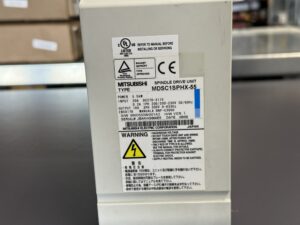
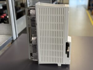
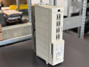
During the incoming inspection, the nameplate data of the unit was recorded and the fault code was compared with the matching Mitsubishi documentation. In addition, the visible assemblies and the installed configuration were documented. According to the attached parts overview, this unit contained a control board RK311C-21 or BN638A170G51 A, a power board RL122B-SP or BN638A153G51 B, and a power section A2-SP55 or BKO-NC1207 H93. This breakdown is important for the assessment because alarm 17 functionally lies exactly in the interaction of these areas. The fault is not only located in the output power section, but in the chain consisting of current measurement, signal processing, conversion and internal evaluation.
In the initial diagnosis, it was therefore important not to jump too quickly to the conclusion of a motor fault. The Mitsubishi documentation does not classify alarm 17 as a classic overvoltage, overcurrent or communication fault, but explicitly as an A/D or current feedback error. That is a clear indication that the actual control variable is not being plausibly acquired or processed.
Especially in cases like this, the incoming inspection is decisive. If you only look at the fault code and immediately replace the complete unit, the actual damage logic remains unclear. In the workshop, it is therefore important first to examine the general condition of the unit, the contact points, the power section, the internal connectors and the thermally stressed areas. Equally important is the question of whether the fault occurs reproducibly or only occasionally. Mitsubishi names exactly this distinction as the first troubleshooting step for alarm 17. If the fault occurs permanently, this strongly suggests an internal defect of the unit. If it occurs only from time to time, ambient influences such as temperature, noise and grounding must also be considered.
Technical analysis
From a technical point of view, this spindle module processes several levels at the same time. It provides the power for the spindle motor, monitors the current consumption, regulates the output to the motor and processes internal feedback signals. The protection logic intervenes as soon as current values can no longer be measured or evaluated plausibly. This is exactly where alarm 17 occurs.
In this case, the cause and effect chain can be described as follows: a disturbance in current sensing or in the downstream analog to digital conversion causes the internal controller to no longer receive clean feedback. Without plausible current feedback, the unit can no longer regulate the output stage safely. The result is a protective shutdown with alarm 17. So the fault does not necessarily mean that the motor already has a severe winding defect. Very often, the actual cause is internal, in the signal conditioning, in an aged measuring chain, in thermally stressed connections, in a disturbed supply of the evaluation electronics, or in a defect on the power board or the control level. The Mitsubishi documentation describes the corrective action for repeatable occurrence as replacement of the unit and, in the case of sporadic occurrence, points to ambient factors. This fits well with typical workshop findings on older spindle inverters.
According to the nameplate, the unit dates from 2006. In this age class, thermal aging, contact problems at internal transitions and loading of the power electronic assemblies play a major role. Particularly critical are areas in which measured signals from the power path have to be transferred electrically cleanly and with low interference to the evaluation stage. Even slight drift, contact problems or interference can trigger implausible current feedback there. The fact that Mitsubishi explicitly names grounding, ambient temperature and interference in the troubleshooting for this alarm is therefore understandable.
Repair measures and overhaul
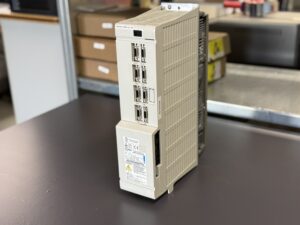
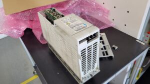
During the repair process, the spindle module was fully opened, cleaned and functionally assessed. The fault search was not reduced to a single component, but focused on the affected functional areas. The control level, the power level, the internal current feedback and the relevant connection points between the assemblies were checked. Based on the available parts list, the fault relevant functional units were clearly assigned. The workshop measures included technical cleaning, inspection of the internal plug and contact areas, assessment of thermally stressed zones and repair or replacement of the affected functional assemblies in the area of the control board, the power board and the power section.
It was important that alarm 17 was not treated like a pure power fault. A drive can fail even with an intact output stage if the current values are no longer reliably processed internally. Accordingly, the repair was aimed at stable signal processing and safe control. As a preventive measure, stressed contact points and age related areas were also included so that the fault not only disappears briefly, but also remains stable under real thermal conditions.
As a preventive measure for units of this type, it is always sensible to also assess the cooling, the cabinet conditions, the power supply and the grounding of the machine. Especially in older spindle modules, increased temperature, contaminated airflow or unfavorable interference often cause internal measuring and control signals to lose stability. This is not always the primary cause, but it significantly intensifies existing weaknesses. Mitsubishi explicitly names these points in connection with alarm 17.
Final functional test
After the repair, the unit was tested on the test bench under controlled conditions. The goal was not only a simple power up, but confirmation that the unit builds up enable cleanly, runs stably and no renewed fault in the current feedback occurs. The test included power on and power off behavior, behavior after repeated starts, response at low and medium speed commands and the general stability of the control.
It was particularly important to observe whether the original alarm 17 could be reproduced or whether the current sensing remained plausible even under changing thermal load. In addition, attention was paid to clean acceleration, stable control behavior and inconspicuous signal processing. Mitsubishi describes that on its spindle and servo units, alarms are displayed on the front via alarm numbers and that in the event of a fault a defined stop behavior is initiated. In the tested condition, no renewed A/D fault pattern could be detected.
The result of the final test was stable. The spindle module could once again be enabled reproducibly and worked in the test run without renewed alarm 17. This meant that the fault had been technically identified, repaired and verified in functional operation.
Conclusion
The present damage was not a typical external short circuit case, but an internal fault in a safety relevant area of the control system. In Mitsubishi terminology, alarm 17 stands for an A/D converter error or for a fault in the current feedback. That is exactly why this case was technically more demanding than the alarm number alone might suggest at first glance. The decisive point was the clean separation between a power fault, a wiring fault and an internal measurement or evaluation problem.
After the technical overhaul and the final test bench inspection, the unit could once again be operated stably. The repair becomes sustainable above all when not only the drive itself, but also the ambient conditions in the machine are correct. Clean cooling, safe grounding, stable supply and regular visual inspection reduce the risk that a fault in the measuring and control chain will occur again.
More details about our Mitsubishi repair services can be found here:
Mitsubishi drive Repair by Industrypart
📞 Feel free to contact us with any questions about your Mitsubishi drive technology.
Our expert team is happy to help!
Technical Specifications
| Field | Value |
|---|
| Manufacturer | Mitsubishi Electric |
| Device type | Spindle Drive Unit |
| Model designation | MDS-C1-SPHX-55 |
| Series | MDS-C1 |
| Power | 5.5 kW |
| Input voltage | DC 270 to 311 V intermediate circuit, plus 1~ 200 to 230 V auxiliary supply, 50/60 Hz |
| Output voltage | 3~ 200 V, 0 to 833 Hz |
| Rated current | Input approx. 20 A DC, output 18 A |
| Control type | regulated spindle drive with internal current feedback and A/D evaluation |
| Feedback | spindle side feedback, depending on configuration via motor detector/feedback device |
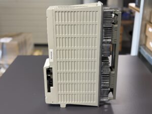
| Cooling | air cooled, heat sink and internal airflow |
| Protection class | approx. IP20 as a cabinet installed unit |
| Ambient temperature | approx. 0 to 55 °C in cabinet operation |
| Mounting | control cabinet, vertical mounting with sufficient cooling |
| Origin | Japan |
| Product status | older existing series, typically found in service and retrofit environments |
| Production date | 08/06 |
| Manual reference | Manual BNP-C3000 according to the nameplate, alarm references from Mitsubishi MDS-C1 and MDS-D/DH documents |
Operating environment and application possibilities
The MDS-C1-SPHX-55 is a spindle drive for machine tools with a regulated main spindle. Typical places of use are machining centers, lathes and machines with regulated spindle drives in the medium power range. The unit operates in a control cabinet and requires stable cooling, a clean electrical environment and reliable grounding.
Typical years of manufacture are in the early to mid 2000s. In practice, this series is still often found in existing machines, especially where the mechanical machine is still serviceable and only the electronics have become service relevant.
Typical applications are:
machine main spindles, regulated speed ranges, acceleration and braking processes, speed stability under load, quick response to load changes.
Requirements for environment and control cabinet:
clean airflow, no excessive oil mist exposure, controlled temperature, reliable shielding and grounding, no unnecessary parallel routing of power and signal lines. In the context of A/D related faults, Mitsubishi explicitly names temperature, interference and grounding as items to be checked.
Notes on thermal and electrical loading:
frequent acceleration and deceleration, high cabinet temperature and aged contact points place a disproportionate load on these units. The measuring and control chain in particular reacts sensitively to thermal drift and electrical interference.
Functional description
Basic function:
The spindle drive converts the supplied power into a regulated three phase output for the spindle motor. In doing so, it monitors current, internal voltages, temperature and feedback signals.
Interaction of power section, control and feedback:
The power section generates the output for the motor. The control system processes command values and feedback. Current feedback is used to acquire the actual motor current and make it available for the control system. This is exactly where alarm 17 is triggered if the A/D acquisition or the current feedback becomes implausible.
Enable:
After switching on, an internal initialization takes place. Only when the internal states are plausible is the unit enabled. Faults in current feedback, parameterization or communication prevent this state.
Protection logic:
The protective functions include undervoltage, overcurrent, overvoltage, overtemperature, regeneration faults, communication faults and feedback faults. In the event of an alarm, a defined stop behavior is triggered.
Thermal monitoring:
The unit monitors the power section and thermally critical zones. High ambient temperature or insufficient airflow can promote consequential damage or unstable signal acquisition.
Signal monitoring:
Feedback data, current signals and communication data are monitored for plausibility. Deviations lead to protective shutdown because safe control is not possible without reliable feedback.
Why these functions are safety relevant:
A spindle drive works directly with rotating masses. Incorrect current acquisition or implausible feedback can lead to uncontrolled behavior, false shutdowns or consequential damage to the motor and the machine. For that reason, the internal signal monitoring is not a convenience feature, but a central part of operational safety.
Alarm messages and troubleshooting
| Alarm code | Description | Possible cause | Recommended action |
|---|
| 10 | Insufficient voltage | bus voltage in the main circuit too low | check supply and contactor |
| 11 | Axis selection error | incorrect axis assignment or setting | check switch or parameterization |
| 12 | Memory error 1 | hardware error during self test | inspect or replace unit |
| 13 | Software processing error 1 | internal software sequence faulty | check repeatability and environment, then replace unit |
| 17 | A/D converter error | fault in current feedback or A/D acquisition | if repeatable, repair/replace unit, also check temperature, grounding and interference |
| 18 | Main side detector initial communication error | communication fault to motor side detector | check parameters, connectors and detector cable |
| 22 | Detector data error | faulty feedback data | check detector, cable and signal quality |
| 30 | Over regeneration | regenerative resistor overloaded | check braking energy, parameters and regeneration path |
| 31 | Overspeed | motor speed above allowable value | check parameters, feedback and acceleration behavior |
| 32 | Power module error overcurrent | overcurrent in power module | check motor, power cable, insulation and power module |
| 33 | Overvoltage | intermediate circuit voltage too high | check supply, braking circuit and deceleration |
| 34 | NC communication CRC error | faulty data from NC | check optical communication or communication link |
| 36 | NC communication error | communication to NC interrupted | check communication connections |
| 3A | Overcurrent | motor current too high | check vibration, load changes, parameters and motor |
| 3B | Power module error overheat | power module overheated | check fan, cooling and environment |
| 46 | Motor overheat / Thermal error | motor or thermal signal overheated/faulty | check motor, fan, thermal signal and load |
| 50 | Overload 1 | motor or drive overloaded | check load, resonance, brakes and parameters |
| 51 | Overload 2 | high current command over longer time | check supply, motor connection, load and feedback |
| 53 | Excessive error 2 | position deviation too high with servo OFF | check brake function and axis movement |
| 88 | Watchdog | system does not operate correctly internally | check repeatability and environment, replace unit |
Assembly overview
| Assembly | Functional designation | Function | Notes for inspection or repair |
|---|
| Control board | RK311C-21 / BN638A170G51 A | internal control, signal processing, evaluation | check for stable supply, signal processing and thermal stress |
| Power board | RL122B-SP / BN638A153G51 B | link between control, current acquisition and power level | especially relevant for alarm 17, pay attention to measuring chain and transitions |
| Power section | A2-SP55 / BKO-NC1207 H93 | power conversion to the motor | inspect for overcurrent, overheating and stress marks |
| Cooling area | heat sink and airflow | thermal stability of the power electronics | check for contamination and ventilation |
| Connection area | power and signal terminals | safe energy and signal coupling | check contact quality, shielding and grounding |
| Feedback interface | detector/encoder input | processes feedback signals for control | inspect connectors, cable and plausibility |
| Intermediate circuit area | DC supply level | supplies the power stage | pay attention to voltage stability and discharge state |