20.12.2025 by Viktor Siebert
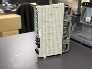
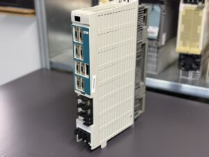
Repair of a Mitsubishi Servo Drive Unit MDS-C1-V2-3520S
Initial situation and fault symptoms
The Mitsubishi Servo Drive Unit MDS-C1-V2-3520S was sent to us with a particularly tricky fault description. The customer reported that the second axis vibrated noticeably at certain speeds. What made this case special was the fact that no classic alarms or fault messages were generated. The machine basically started, positioned, and operated, but at around 1500 revolutions per minute the motor showed strong and reproducible vibration.
This case was especially delicate due to its history. The unit had previously been tested by a competitor. There, the drive was checked and declared fault-free. According to the feedback, everything was running normally. However, in the machine itself the problem persisted, which understandably unsettled the customer.
Incoming inspection and initial analysis
After the unit arrived at our facility, a standardized incoming inspection was carried out. Visual inspection, documentation of the nameplate, verification of the serial number, and an initial electrical basic check revealed no obvious abnormalities. No burn marks or major damage were visible.
At this stage, one decisive point already became clear. Faults like this cannot be detected on the bench or with a simple functional test. For this reason, the unit was put into operation on our servo test bench under realistic conditions. We simulate loads, speed ranges, and dynamic transitions as they occur in real machines.
Reproducibility of the fault
Under load and during targeted speed runs, the fault could be clearly reproduced. Exactly in the range around 1500 rpm, the second axis showed pronounced mechanical instability. This did not appear as random noise, but as a clearly perceptible and measurable vibration. The first axis, by contrast, ran smoothly and quietly.
This behavior is a textbook example of why unprofessional or overly simple test environments fail to reveal such faults. Without load, without defined speed ramps, and without precise measurement equipment, this type of problem remains invisible.
Diagnosis and root cause
Further analysis focused on the power and driver stage of the affected axis. Measurements of the current waveforms showed slight asymmetries that were still within the protection limits but caused instability in the control loop. These instabilities are transmitted directly to the motor and manifest themselves mechanically as vibration.
The root cause was found in the driver output stage of the second axis. Age-related component drift and early-stage degradation led to the power semiconductors no longer being driven in a perfectly symmetrical manner. In such cases, a classic alarm is often not triggered because the formal limit values are not exceeded.
Repair and preventive overhaul
After the diagnosis was clearly established, the affected driver output stage was repaired. In addition, the entire unit was preventively overhauled. This included, among other things, the inspection and replacement of critical components in the power and control sections, thorough cleaning, and checking of all connectors and solder joints.
This preventive approach is particularly advisable for MDS-C1 drives, as many components have now reached an age where failures do not occur suddenly, but gradually.
Final test and result
After completion of the repair, the MDS-C1-V2-3520S was tested again on the test bench. All relevant speed ranges were run through multiple times, both with and without load. The previously clearly noticeable vibration at 1500 rpm was completely eliminated. Both axes ran smoothly, stably, and symmetrically.
The unit was then documented, approved, and returned to the customer. The result was unambiguous. The drive is fully operational again and prepared for continued long-term use.
Preventive measures for the customer
One of the key lessons from this case is the importance of a professional test environment. Many faults do not arise from total failure, but from gradual changes in the electronics. These often only become apparent under specific operating conditions.
Regular inspection of drives is recommended, especially in older systems. Preventive overhauls can help avoid unplanned machine downtime and significantly extend the service life of the components.
Conclusion
The Mitsubishi Servo Drive Unit MDS-C1-V2-3520S clearly demonstrates how demanding troubleshooting of modern CNC servo drives can be. A unit may appear inconspicuous at first glance and during simple tests, while clearly causing problems under real operating conditions.
Only with an appropriate test environment, deep system understanding, and experience can such faults be reliably identified and sustainably resolved. In this case, full functionality was restored through targeted repair of the driver output stage and a comprehensive preventive overhaul.
To mentioned Mitsubishi Drive: Mitsubishi Servo Drive Unit MDS-C1-V2-3520S
More details about our Mitsubishi repair services can be found here:
Mitsubishi drive Repair by Industrypart
📞 Feel free to contact us with any questions about your Mitsubishi drive technology.
Our expert team is happy to help!
Technical Specifications
| Feature | Value |
|---|
| Manufacturer | Mitsubishi Electric |
| Type | MDS-C1-V2-3520S |
| Series | MDS-C1 |
| Axes | 2-axis servo drive |
| Rated power | 3.5 kW / 2.0 kW |
| DC link | DC 270–311 V |
| Input | Single-phase 200–230 V AC, 50/60 Hz |
| Output | Three-phase 155 V, 0–240 Hz |
| Output current | 16 A / 13 A |
| Cooling | Forced cooling |
| Manual | BNP-C3000 |
| Year of manufacture | 2011 |
| Origin | Japan |
Application environment and compatible equipment
The Mitsubishi MDS-C1-V2 series is typically used in CNC machine tools, including machining centers, lathes, and complex multi-channel systems. The 3520S model is designed for applications where two axes must be controlled precisely and synchronously. Typical applications include feed axes, rotary axes, or combined axis groups with high demands on smooth running and dynamics.
The unit is compatible with a wide range of Mitsubishi servo motors of the corresponding power class. Control is carried out via Mitsubishi CNC controls, where parameters, control loops, and monitoring functions are closely matched to the drive hardware.
Functional description
The MDS-C1-V2-3520S is a dual-axis digital servo drive that supplies, controls, and monitors the connected servo motors. Internally, separate power stages are used for each axis, combined with a shared control logic. Control is based on current, speed, and position control loops that are processed in real time.
Special attention is paid to clean current control and symmetrical activation of the power modules. Even very small deviations in the driver stage or in the current measurement path do not necessarily trigger a classic alarm, but can instead manifest themselves as mechanical instability, vibration, or resonance. This is precisely where one of the major challenges in troubleshooting such units lies.
Components
| Assembly | Designation | Function |
|---|
| Control board | RK11A2A-22 / BN634A980G51 | Central control and communication |
| Power board | RL12B2-V2 / BN634A153G51 | Control of the power modules |
| Power section | BKO-NC1207 H94 A2-V2-3520S | Energy conversion for the motors |
| Alarm Code | Alarm Name | Description | Practical Relevance |
|---|
| 23 | Excessive speed error | Deviation between commanded speed and actual speed | Can occur with an unstable control loop |
| 32 | Power module overcurrent | Overcurrent detected in the power module | Often related to defective or unstable driver stages |
| 50 | Overload 1 | Thermal overload of motor or drive | Typical consequence of vibration or resonance |
| 51 | Overload 2 | Continuous high current close to maximum limit | Common with asymmetric or drifting power stages |
| 52 | Excessive error 1 | Position deviation exceeds allowable limit | Often accompanies axis vibration or control instability |
| 3A | Overcurrent | Short-term overcurrent detected | May occur sporadically without a clear alarm history |
| 88 | Watchdog | Internal control error detected | Frequently linked to unstable or aging electronics |