17.04.2026 by Viktor Siebert
Mitsubishi Servo Drive Unit MDS-B-V2-1010 with No Power Up Response, Failed Cooling Fan, Internal Power Supply Failure and Power Section Damage
Initial Situation and Fault Pattern.
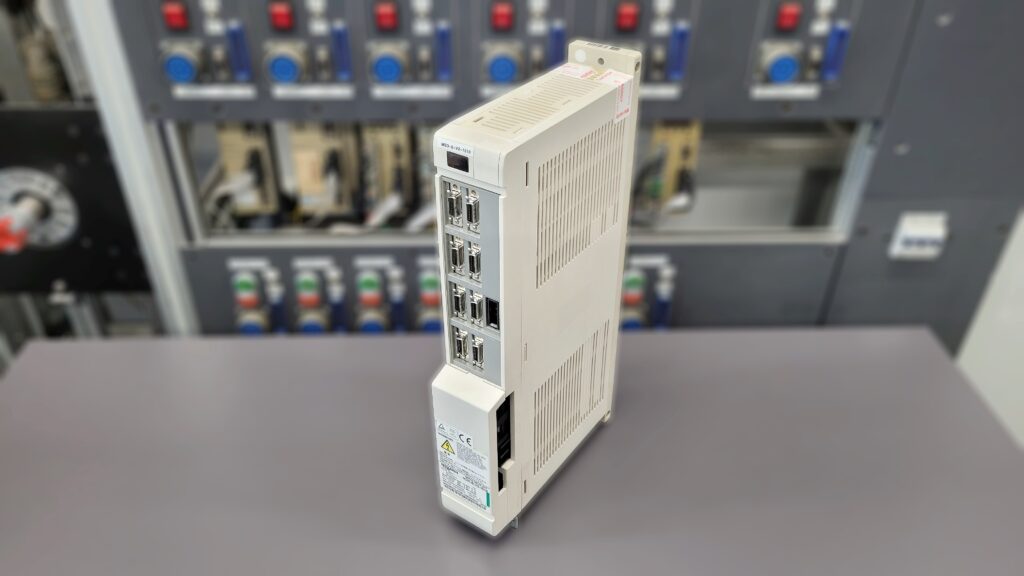
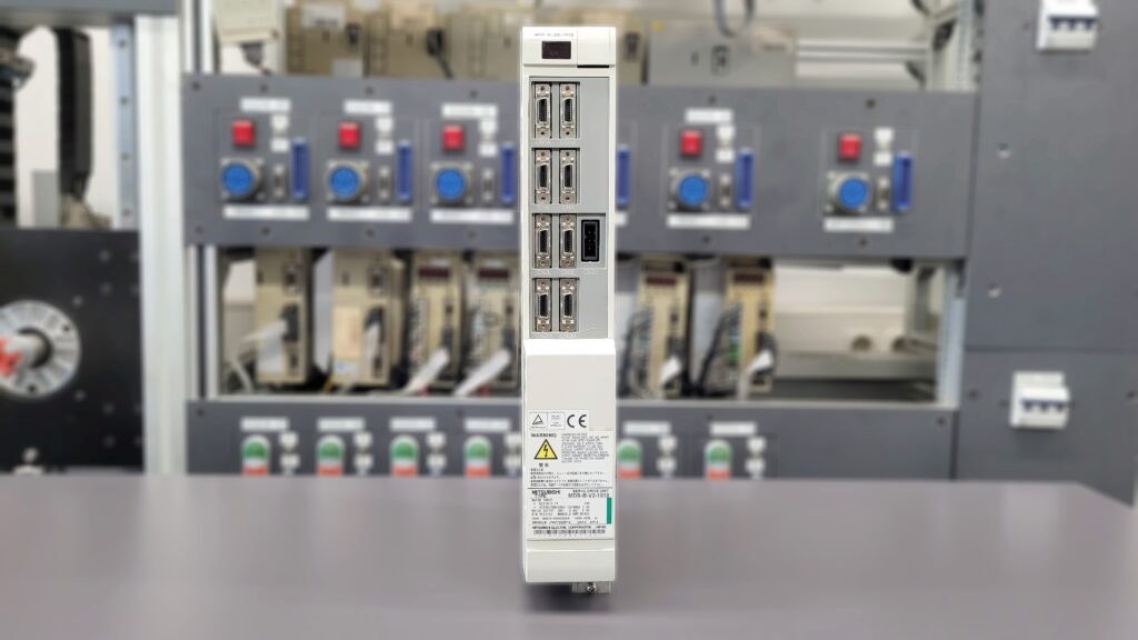
This repair case involved a Mitsubishi Servo Drive Unit MDS-B-V2-1010. When switched on, the unit showed absolutely no reaction. No LED lit up, the fan did not start, and the module remained completely without any sign of life. This is exactly how the unit arrived at our facility. The fault could be reproduced in the machine. There as well, the drive remained completely dead after switch on.
Technically, the fault pattern was conspicuous because not only was the power stage enable missing, but the basic internal supply of the unit did not even start. If on a servo drive neither the status display nor the fan function is present, the damage in many cases is no longer limited to a single protective shutdown, but lies deeper in the internal supply or in the power section. In such cases, a pure external inspection is not sufficient. The unit must be opened and its internal condition must be assessed properly.
The safe procedure is always important here. Before opening the unit or disconnecting plugs, it must be de energized, secured against being switched on again, the discharge time must be observed, and absence of voltage must be verified. Measurements on live parts may only be carried out by qualified electrical personnel with suitable equipment and in accordance with local regulations.
Incoming Inspection and Initial Diagnosis
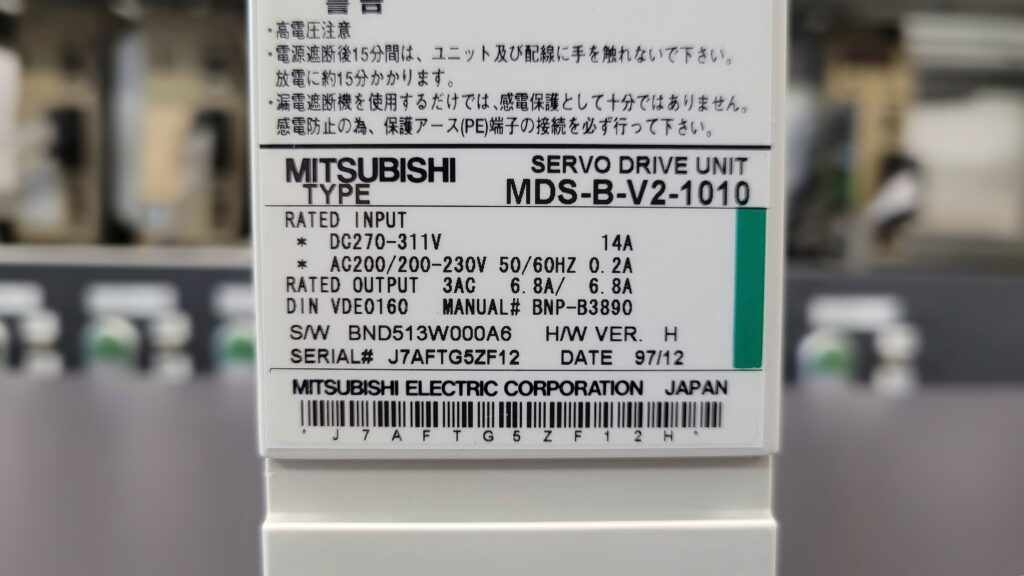
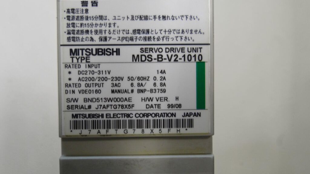
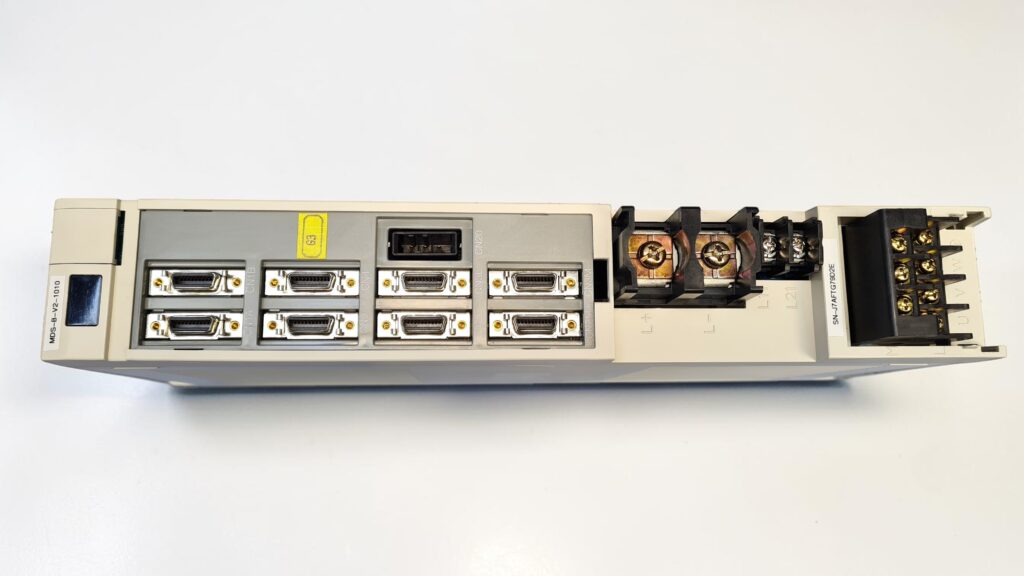
During the incoming inspection, the nameplate was first recorded. It is a Mitsubishi Servo Drive Unit MDS-B-V2-1010 with a production date of 99/08. Among other things, the unit is marked with a DC input of 270 to 311 V, a control input of AC 200 to 230 V at 50/60 Hz, and a 3AC output with 6.8 A. The origin is Japan. This matches an older CNC servo drive from machine tool applications.
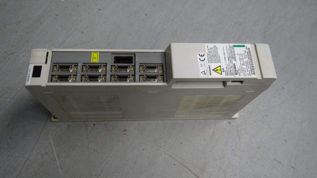
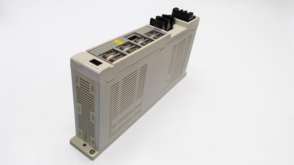
After confirming the fault in the machine, the unit was disassembled. The fan immediately stood out. Even during removal, it became apparent that it was no longer mechanically free running. The fan was completely clogged with dirt and did not rotate anymore. This is not a secondary issue, but in many cases the starting point of a longer thermal overload process. If forced cooling fails, the temperature inside the unit rises significantly in the thermally critical areas. This affects not only the power section, but also the internal supply.
The first diagnosis was therefore clearly narrowed down very early. There was no single communication fault and no sporadic alarm condition, but a genuine hardware failure with consequential damage.
Technical Analysis
In this unit, the cause and effect chain is plausible and can be followed well in the workshop. The fan was blocked by heavy contamination. As a result, cooling failed during operation, or at least was severely restricted over a longer period. The power loss heat inside the unit could no longer be dissipated sufficiently. Under this thermal stress, the internal supply first weakened and was eventually damaged. If the internal supply collapses, the drive remains completely dead when switched on. This was exactly the symptom present here.
In addition, further inspection showed that the power output stage had also already been affected. This is a typical consequential failure when a drive has been operated close to its thermal limit over a longer period. The temperature stress does not act only at one point, but affects several functional assemblies at the same time. Critical power components age faster, transitions are stressed, and protective reserves are lost. At some point, the condition is reached where the unit no longer starts.
This also explains why the damage initially appears from the outside as a pure total failure. In reality, however, the cause often lies some time in the past. In this case, the blocked fan was the clear technical starting point. The actual symptom of no LED and no fan function was already the result of advanced internal damage.
Repair Measures and Overhaul
During the repair process, the drive was completely disassembled and first thoroughly cleaned. On units like this, cleaning is not only important for appearance. Deposits obstruct heat dissipation, make evaluation more difficult, and in combination with moisture or conductive dust can cause additional faults.
After that, the affected functional groups were technically repaired. The internal power supply was repaired, the damaged areas in the power section were reworked, and functionally damaged units were replaced. This was not documented on an individual component level, but by testing and repairing the assemblies and functional areas. At the same time, cooling was restored so that the original cause of the damage would not remain inside the unit.
From a preventive standpoint, it is important with this type of damage pattern to always assess the air flow and the condition of the fan fundamentally. Older drives in contaminated control cabinets often fail not only because of electrical aging, but very frequently because cooling performance deteriorates. Therefore, checking the forced ventilation is an essential part of a sustainable repair.
Final Functional Test
After the repair, the unit was electrically tested and checked for function. The decisive point at first was the power on and power off behavior. The drive had to start up cleanly again, build up the internal supply stably, and show reproducible switch on behavior. After that, the output function was checked under suitable test conditions.
During the test run, attention was paid to stable starting behavior, clean supply, unobtrusive thermal behavior, and the function of the power section. In addition, it was observed whether the unit would become abnormal again under load changes or over a longer operating time. Especially after damage caused by thermal overload, temperature monitoring is particularly important.
The functional test was unobtrusive after the repair. The unit started correctly again, the supply remained stable, and the power output was reproducibly present. This meant that the technical basic function had been restored.
Conclusion
The damage to this Mitsubishi MDS-B-V2-1010 was not a spontaneous isolated defect, but the result of failed cooling. The completely clogged and blocked fan very likely led over a longer period to thermal overload. This resulted in damage to the internal power supply and in the power section. The external fault pattern with no LED and no fan function was already the final stage of this development.
The repair is sustainable because not only the visible total failure was corrected, but also the technical cause and the thermally stressed functional areas were taken into account. That is exactly what is crucial with older industrial drives.
Technical Specifications
| Field | Specification |
|---|
| Manufacturer | Mitsubishi Electric Corporation |
| Unit type | Servo Drive Unit |
| Model designation | MDS-B-V2-1010 |
| Series | MDS-B-V2 |
| Power | approx. 1.0 kW class |
| Input voltage | DC 270 to 311 V, additionally AC 200 to 230 V, 50/60 Hz |
| Output voltage | 3AC, supplied from DC bus, exact output voltage load dependent |
| Rated current | 3AC 6.8 A / 6.8 A |
| Control type | CNC servo drive, controlled AC servo drive |
| Feedback | application dependent via motor feedback / position feedback, machine specific |
| Cooling | Forced cooling with fan |
| Protection class | approx. IP20, control cabinet unit |
| Ambient temperature | approx. 0 to 45 °C, depending on control cabinet and cooling situation |
| Mounting | Control cabinet mounting |
| Origin | Japan |
| Product status | Existing unit, older series, repair economically relevant |
Operating Environment and Application Possibilities
The MDS-B-V2-1010 is typical for CNC machines with Mitsubishi drive technology. Such units are found, among others, in machining centers, lathes, machine tools, and special purpose machines with controlled feed axes.
According to the nameplate, the specific unit dates from 99/08. This places the typical period of use in the late 1990s and early 2000s. In many machines, these series are still in operation today, provided that the control cabinet climate, cooling, and plug connections are in proper condition.
Typical applications are feed axes with dynamic acceleration and braking cycles. This results in high demands on thermal resilience, cooling cleanliness, and supply quality. The control cabinet must provide sufficient airflow, low dust contamination, and stable voltage conditions. Contaminated fans, clogged cooling paths, and continuous thermal stress significantly increase the risk of failure.
Functional Description
The drive converts the supplied DC bus voltage into a controlled three phase motor output and turns the motion commands specified by the CNC into current, torque, and axis movement. For this purpose, the power section, internal supply, and control work closely together.
The power section generates the motor output from the DC bus. The control processes command values and feedback. The internal supply ensures that logic, monitoring, and driver stages start up stably. If this supply fails, the unit remains without function already during switch on. This was exactly the fault pattern present here.
The drive enable is only issued when the internal conditions are fulfilled. These include stable supply, fault free internal communication, and intact protective logic. The protective logic monitors, among other things, voltage conditions, overcurrent, feedback, and internal fault states. These functions are safety relevant because they bring the unit and the machine into a safe stop or into a blocked start condition in the event of impermissible operating states.
Alarm Messages and Troubleshooting
| Alarm code | Description | Possible cause | Recommended measure |
|---|
| 11 | Axis selection error | Incorrect axis selector switch setting | Check and correctly set the axis address |
| 12 | Memory error 1 | Hardware fault in self test during switch on | Check the drive, repair or replace if repeatable |
| 13 | Software processing error 1 | Error in software sequence | Check repeatability, environmental conditions, and unit |
| 16 | Pole position detection error | Magnetic pole detection incorrect or not set | Check parameterization and pole detection |
| 17 | A/D converter error | Error in current feedback | Electrically test and repair the drive |
| 18 | Main side detector initial communication error | Communication fault with motor side feedback | Check encoder, cable, and plug connections |
| 1A | Sub side detector initial communication error | Communication fault with machine side feedback | Check feedback, cable, and parameters |
| 22 | Detector data error | Faulty feedback data | Check detector mounting, cable, and environmental interference |
| 24 | Grounding | Motor cable to FG or ground fault | Measure insulation, check motor and power cable |
| 30 | Over regeneration | Braking energy too high, braking resistor overloaded | Check braking circuit, parameters, and deceleration |
| 31 | Overspeed | Motor speed above permissible range | Check feedback, parameterization, and acceleration |
| 32 | Power module error overcurrent | Overcurrent in power section | Check motor, power cable, insulation, and drive |
| 33 | Overvoltage | DC bus voltage too high | Check supply, braking circuit, and deceleration |
| 3A | Overcurrent | Motor current too high | Check load, control, feedback, and power section |
| 3B | Power module error overheat | Overtemperature in power module | Check fan, cooling surfaces, and control cabinet temperature |
| 3C | Regeneration circuit error | Fault in braking branch or braking resistor | Electrically test regenerative circuit |
| 45 | Fan stop | Fan stopped with resulting overheating risk | Check fan function and contamination |
| 46 | Motor overheat / Thermal error | Motor or thermal signal above temperature limit | Check load, cooling, thermal circuit, and motor |
| 50 | Overload 1 | Motor or drive overloaded | Check load profile, parameters, and mechanics |
| 51 | Overload 2 | High current over a longer period | Check current trend, load, and motor circuit |
The alarm designations and the recommended basic measures come from the Mitsubishi Alarm and Troubleshooting document for the MDS-A/B Series. Among others, alarms 11, 12, 13, 17, 18, 1A, 22, 24, 30, 31, 32, 33, 3B, 45, 46, 50 and 51 are documented there.
Assembly Overview
| Assembly | Functional designation | Function | Notes for inspection or repair |
|---|
| Control board | RK111A-12 or BN634A768G51 A / RK111B-12 or BN634A815G51 D | Control, logic, internal signal processing | Check visually, test supply, signal processing, and thermal stress |
| Power board | RK156B-V2-1010 or BN634A811G51A | Power output to the motor | Check for short circuit, thermal damage, and function |
| Internal power supply | Functional unit | Supply of logic and driver stages | Check first in the event of total failure |
| Fan unit | Forced cooling | Heat dissipation inside the unit | Check free movement, contamination, and starting behavior |
| Heatsink / thermal path | Functional unit | Dissipation of power loss heat | Check for contamination and sufficient airflow |
| Power connections | DC bus and motor output | Energy input and motor output | Check terminals, transitions, and insulation |
| Signal and feedback interfaces | Functional unit | Connection to control and encoder | Check plug condition, contact pattern, and cable condition |