23.03.2026 by Viktor Siebert
Mitsubishi Servo Drive Unit MDS-B-V1-10 with Alarm 17 under thermal load and axis load
Starting situation and fault pattern.
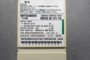
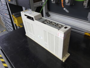
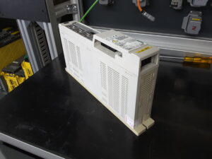
This repair case involved a Mitsubishi Servo Drive Unit MDS-B-V1-10. According to the nameplate, this is a servo drive from the MDS-B series with DC bus input from DC270 to 311 V, additional control voltage AC200 to 230 V, and an output of 3AC 6.8 A. The unit dates from 09/1996. The reported fault was Alarm 17. In the alarm table of the MDS-A/B series, Alarm 17 is described as an A/D converter error, meaning a fault in the current feedback or A/D acquisition in the power amplifier.
What was particularly noticeable was the timing of the fault. At first, the error was not permanently present. According to the customer, it had been occurring sporadically for a longer period, especially during the warm summer months. Later, the failure became much more frequent. Most recently, the alarm already appeared after one to two hours of machining. In addition, the customer noticed a clear connection with programs in which the X axis was more heavily loaded. This exact connection was technically important. When a fault occurs depending on load, temperature, and is not immediately reproducible, this is often an indication of a damaged power stage or aged assemblies in the current acquisition.
So the unit was still basically running, but only until temperature and load came together. Fault patterns like this are tricky in practice because in the cold state they can quickly appear inconspicuous. In the installed state, this often leads to the fault initially being interpreted as a machine problem, wiring problem, or even an axis problem. The actual cause, however, lies in the drive itself.
Before opening the unit or disconnecting plugs, always switch it off without voltage, secure it against being switched on again, wait for the discharge time, and verify absence of voltage. Measurements on live parts must only be carried out by a qualified electrician with suitable equipment and in accordance with local rules.
Incoming inspection and initial diagnosis
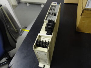
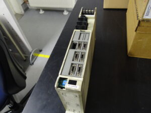
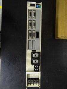
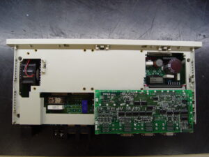
During the incoming inspection, we first checked the nameplate, design, and assembly. Based on the available photos and the parts overview, this unit contains, among other things, a control board marked RK111B-11 or BN634A815G51 D and a power board marked RK156B-V1-10 or BN634A811G51 B. This matches the design of an MDS-B servo drive with separate control and power sections.
After that, the usual visual inspection was carried out for contamination, thermal abnormalities, contact problems, and signs of aging. With units from the 1990s like this, we pay particular attention to thermally stressed areas, contact points, power connections, and assemblies that have been cyclically heated and cooled again over many years. Especially when a fault is described as load and temperature dependent, the probability is high that the unit will initially start normally under laboratory conditions.
The decisive point was therefore reproduction on the test bench. The drive was operated in our test setup and deliberately subjected to thermal load. In the cold state, the behavior was initially inconspicuous. Under heating, however, the fault could be provoked repeatedly. This exactly confirmed the customer’s description. As soon as temperature entered the unit, the alarm appeared reproducibly. This made it clear that there was not just a one-time dropout or an external disturbance, but an internal, temperature-dependent defect.
Technical analysis
From a technical point of view, Alarm 17 in the MDS-A/B series is assigned to the area of A/D conversion and current feedback. In this area, internal actual values from the power section are converted into a form that can be evaluated by the control section. If this acquisition becomes unstable under load, the control can no longer properly assess the actual motor current. This does not necessarily lead immediately to failure in the cold state, but it does under thermal load.
The cause and effect chain was plausible here. Over the years, functional areas of the power stage had aged. At normal temperature, the signals were still in a range in which the unit could operate. With increasing heating, however, the electrical properties changed to such an extent that the current acquisition or the associated processing became implausible. The result was Alarm 17. The fact that the fault occurred especially with the more heavily loaded X axis also fits this. Higher axis load means higher current demand, more thermal stress in the power section, and therefore quicker reaching of the critical condition.
From a workshop point of view, this is a typical example of why a unit can still partially function for a long time despite a real defect. As long as temperature, load, and tolerance position still just fit together, the drive appears to run normally. Only during longer machining or with critical machining programs does the condition tip over. This is exactly why short tests alone are often not sufficient.
Repair measures and refurbishment
Since the fault could be clearly identified as load and temperature dependent in the power section area, we overhauled the power stage of this unit preventively. For this, the unit was opened, cleaned, and the affected functional areas were systematically checked. Aged and thermally conspicuous components in the power assembly were repaired or renewed. We deliberately do not go into individual component level here, the functional statement is decisive. The aim was to restore stable behavior of the power section and the associated acquisition under load and temperature.
In addition, typical weak points of this assembly were taken into account with a view to long-term stability. This is exactly where the practical benefit of clean workshop documentation lies. If a certain damage-relevant pattern is confirmed on a unit of this series, this knowledge can be directly incorporated into the standard process for future repairs. This saves time, reduces variation in diagnosis, and increases the hit rate for preventive overhauls.
In this case, that was especially important because the fault pattern was not a hard permanent failure, but an intermittent thermal load fault. Without documentation, it would be easy to start again from zero on the next unit. With documented damage history, such drives can be specifically and sensibly overhauled in a standardized way.
Final function test
After the repair, the final test was again carried out on the test bench. Here, not only a short startup was checked, but a load and temperature test was deliberately performed. This is the decisive point with this fault pattern. A cold start without load would not have provided a reliable statement.
Tested were switch on and switch off behavior, stable enable behavior, signal processing under load, and behavior during longer running time. In addition, the unit was thermally monitored to ensure that the previously reproducible fault no longer appeared. Even during longer test duration and under increased load, the behavior remained stable. The alarm did not reappear.
This exact load completion test is important. For us, a drive with a formerly temperature-dependent fault is only considered properly repaired when the function remains stable under heat and load as well. Anything else would be too uncertain with such a fault pattern.
Conclusion
This case shows very well how an internal defect in the power stage can become noticeable over a long period only under certain conditions. Alarm 17 here was not a random individual alarm, but the result of an aged, thermally critical function in the drive. The combination of temperature, machining time, and high X axis load was the decisive indication.
After the overhaul of the power stage and the final test under load, the unit was stable again. The repair is sustainable above all because not only the acute fault was addressed, but the known weak point of the assembly was also functionally taken into account. In this way, the risk of a repeated failure can be significantly reduced.
More details about our Mitsubishi repair services can be found here:
Mitsubishi drive Repair by Industrypart
📞 Feel free to contact us with any questions about your Mitsubishi drive technology.
Our expert team is happy to help!
Technical specifications
| Field | Value |
|---|
| Manufacturer | Mitsubishi Electric Corporation Japan |
| Device type | AC Servo Drive Unit |
| Model designation | MDS-B-V1-10 |
| Series | MDS-B |
| Power | approx. 1.0 kW class range |
| Input voltage | DC270 to 311 V main circuit, AC200 to 230 V 50/60 Hz control circuit |
| Output voltage | 3AC, load-dependent from DC bus |
| Rated current | 6.8 A output, 7 A DC input, 0.2 A AC control circuit |
| Control type | Servo drive with current, speed, and position control |
| Feedback | Motor encoder or detector, depending on system |
| Cooling | Convection cooling via heatsink, depending on control cabinet |
| Protection class | approx. IP20 in control cabinet installation |
| Ambient temperature | approx. 0 to 55 °C with sufficient cooling |
| Mounting | Control cabinet, vertical mounting |
| Origin | Japan |
| Product status | Discontinued, repair economically relevant |
Operating environment and possible applications
The MDS-B-V1-10 was typically used in CNC machine tools. These units are often found in machining centers, lathes, special machines, and older production lines with Mitsubishi or Mazak drive technology. The MDS-B series is designed for axis drives where repeatable positioning, dynamic acceleration, and reliable control are required. In practical terms, the application range is mainly in machines from the 1990s and early 2000s.
Important for operation are a clean control cabinet, stable power supply, good dissipation of power loss heat, and clean contact conditions. Thermal stress, contaminated cooling air paths, aged cabinet fans, or poor grounding significantly increase the probability of failure. Especially with cyclically highly loaded axes, the stress on the power section and current acquisition increases.
Functional description
The drive converts the provided DC bus into a controlled three-phase motor output. In the interaction of power section, control, and feedback, motor current, speed, and position are monitored and controlled. The control processes target values from the CNC and compares them with the actual values detected from the motor or the encoder system.
Enable is provided via the machine control. Protection logics monitor, among other things, undervoltage, overcurrent, overload, feedback faults, and internal plausibility. In the event of faults, the drive is shut down in a controlled manner or dynamically braked, depending on the fault type. These functions are safety-relevant precisely because control errors in the power section can directly lead to axis loss, machine standstill, or consequential damage.
In the case of Alarm 17, the area of internal current feedback and A/D processing is specifically affected. This is a central function because stable control under load is only possible with plausible current values. A fault in this area can therefore begin sporadically, but under temperature it can turn into a reproducible machine standstill.
Alarm messages and troubleshooting
| Alarm code | Description | Possible cause | Recommended measure |
|---|
| 11 | Axis selection error | Incorrect axis addressing or switch setting | Check axis assignment and device setting |
| 12 | Memory error 1 | Internal hardware or memory fault | Check the unit, if repeated repair or replace |
| 13 | Software processing error | Internal processing fault | Check environmental conditions and the unit |
| 17 | A/D converter error | Fault in current feedback or A/D processing | Check power section and current acquisition, perform thermal test |
| 18 | Initial communication error | Communication fault with motor encoder at startup | Check encoder, cable, and parameters |
| 20 | No signal detected 1 | No plausible encoder or position signal | Check feedback and connection |
| 21 | No signal detected 2 | Feedback missing during movement | Check encoder, cable, and parameterization |
| 25 | Absolute position lost | Absolute value information lost | Check battery, cable, feedback, and set reference again |
| 31 | Overspeed | Motor speed above limit value | Check parameters, feedback, and load behavior |
| 32 | Power module overcurrent | Overcurrent in power module | Check motor, wiring, load, and power module |
| 34 | CRC error | Communication fault to the NC | Check communication cable and connection |
| 37 | Parameter error | Implausible or incorrect parameters | Check and correct parameterization |
| 3A | Overcurrent | Excessive motor current | Check load, motor, feedback, and controller setting |
| 3B | Power module overheat | Power module thermally overloaded | Check cooling, ambient temperature, and load |
| 43 | Feedback error 2 | Deviation between feedback systems | Check encoder matching and signal quality |
| 46 | Motor overheat | Motor temperature or thermal protection triggered | Check load, cooling, and motor thermal condition |
| 50 | Overload 1 | Overload limit reached | Reduce load, check motor and drive sizing |
| 51 | Overload 2 | High current present for extended period | Check cycle, load peaks, and current control |
| 52 | Excessive error 1 | Position control deviation too high | Check mechanics, load, and control parameters |
| 53 | Excessive error 2 | Fault in deviation with servo OFF | Check brake, mechanics, and follow-up function |
Assembly overview
| Assembly | Functional designation | Function | Notes for testing or repair |
|---|
| Control board | RK111B-11 / BN634A815G51 D | Control, evaluation, communication | Check for thermal traces, signal stability, and contact problems |
| Power board | RK156B-V1-10 / BN634A811G51 B | Power output to motor, current processing | Particularly relevant in load and temperature dependent faults |
| Heatsink area | Integrated power cooling | Dissipation of power loss heat | Ensure clean heat transfer and cabinet cooling |
| Power connection area | Main and motor terminals | Supply and motor output | Check screw connections and contact condition |
| Feedback connection | Encoder or detector interface | Transfer of actual values to the control | Particularly check for Alarms 17, 18, 20, 21, 43 |
| DC bus area | DC power supply | Energy for the power section | Check voltage stability and thermal abnormalities |
| Alarm and protection logic | Internal monitoring | Protects unit and axis in the event of faults | Evaluate fault history and reproducibility |
| Front and operating elements | Display and parameterization | Diagnosis and status | Check alarm code, axis assignment, and basic condition |