12.02.2026 by Viktor Siebert
Mitsubishi Power Supply Unit MDS-C1-CV-370 Repair Report and Technical Assessment
When “E” Does Not Simply Mean “End”.
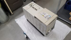
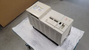
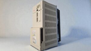
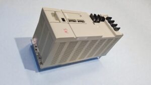
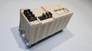
The Mitsubishi Power Supply MDS-C1-CV-370 arrived at our facility with a very typical yet at the same time tricky fault description. The customer reported that immediately after power-up, an “E” alarm appeared on the display. In addition, a clearly audible high-pitched whining noise could be heard from the power supply. The cooling fan did not start. The unit had already been removed from the machine and tested on the bench with 200 V AC input voltage. The fault was reproducible and consistent.
At this point, many maintenance departments and even some repair companies make a quick decision: control board defective, replace it, done. This is exactly where the story shows why we deliberately take a different approach.
Initial Analysis at the Test Bench
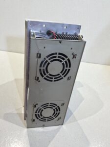
After receiving the unit, a visual inspection was carried out first. No obvious burn marks, no exploded capacitors, no mechanical damage. The power supply was then connected to our isolated test bench with current limitation and oscilloscope monitoring. The behavior fully confirmed the customer’s description:
- The display immediately showed “E”
- A high-frequency whining noise was present
- The cooling fan did not start
- The DC link did not build up stably
This whining noise is a very important indicator. In many cases, it points to a switch-mode power supply that has entered an unstable control state. This is typically caused by faults in the control or feedback electronics, not necessarily in the power section itself.
Diagnosis Instead of Board Replacement
At this stage, it is common practice to replace the entire control board. This is also where we are often asked:
Why not simply replace the board? Wouldn’t that be faster and easier?
The honest answer is: sometimes yes, but in most cases no.
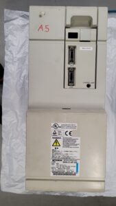
Our developer focused specifically on the control board and checked all relevant voltages, references and clock signals. It became clear that an internal monitoring circuit was providing incorrect feedback to the control logic. As a result, the power supply immediately entered a protective state, even before the fan enable was released. The root cause was not in the power section, but in a small yet critical circuit on component level on the control board.
Component-Level Repair
Instead of replacing the entire, expensive control board, the defective section was repaired at component level. This included:
- Targeted component diagnostics
- Replacement of individual electronic components
- Verification of all relevant reference voltages
- Functional testing under controlled conditions
After the repair, the MDS-C1-CV-370 was powered up again. The whining noise was gone, the fan started normally, the DC link voltage built up cleanly and the alarm no longer appeared.
Why We Do Not Simply Swap Boards Four Clear Reasons
This case is a good example of why we consistently aim to restore the complete device instead of swapping assemblies:
First: Sustainability.
Replacement boards are often only available from donor units. That means another potentially repairable device is dismantled. This is neither sustainable nor aligned with our environmental responsibility.
Second: Cost.
Control boards are expensive. In many cases, the cost of a replacement board is completely disproportionate to the actual defect. Component-level repair is significantly more economical.
Third: Knowledge and speed for future repairs.
Once a fault has been precisely identified, the same issue can be repaired very quickly in future cases. Experience grows, repair times decrease.
Fourth: Parameters and functionality.
A “donor board” does not automatically work out of the box. Control boards often store parameters, calibrations and sometimes machine-specific data. Reprogramming is time-consuming and error-prone. A repaired original board, on the other hand, fits perfectly.
Testing, Load and Release
After successful repair, the power supply was operated on the test bench for several hours. Load changes were simulated, temperatures monitored and DC link stability verified. Only after a fault-free endurance test was the unit approved for return.
Conclusion
This Mitsubishi MDS-C1-CV-370 clearly demonstrates that professional repair means more than replacing parts. With technical understanding, experience and a proper test setup, even complex faults can be resolved sustainably. For the customer, this means lower costs, higher operational reliability and the confidence that no functional equipment was unnecessarily scrapped.
That is exactly what we stand for.
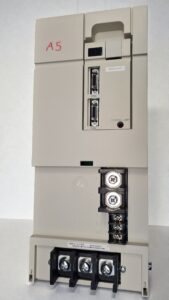
To mentioned Mitsubishi Drive: Mitsubishi Power Supply Unit MDS-C1-CV-370
More details about our Mitsubishi repair services can be found here:
Mitsubishi drive Repair by Industrypart
📞 Feel free to contact us with any questions about your Mitsubishi drive technology.
Our expert team is happy to help!
Technical Block Mitsubishi MDS-C1-CV-370
Technical Specifications
| Parameter | Specification |
|---|
| Manufacturer | Mitsubishi Electric |
| Device Type | Power Supply Unit (DC Link Power Supply) |
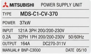
| Model | MDS-C1-CV-370 |
| Series | Mitsubishi MDS-C1 |
| Rated Power | approx. 37 kW |
| Input Voltage (Main Circuit) | 3-phase 200–230 V AC, 50/60 Hz |
| Input Current (Main Circuit) | approx. 121 A |
| Control Power Supply | Single-phase 200–230 V AC |
| Output Voltage | DC 270–311 V |
| Output Current | max. approx. 164 A |
| Cooling | Forced air cooling (integrated fan) |
| Protection Class | IP20 |
| Mounting | Control cabinet, vertical |
| Weight | approx. 18–22 kg |
| Production Year | approx. 2010 |
| Standards | EN50178 |
| Manual Reference | Mitsubishi MDS-C1 / C1-CV Series |
Application Environment and Compatible Systems
| Category | Description |
|---|
| Typical Application | CNC machine tools |
| System Function | Central DC link power supply |
| Supplied Units | Servo drives, spindle amplifiers |
| Compatible Series | Mitsubishi MDS-C1 servo and spindle modules |
| Typical Machines | Machining centers, lathes, transfer lines |
| Ambient Temperature | 0 °C to +55 °C |
| Installation Environment | Control cabinet with forced airflow |
| Cooling Requirements | Free air circulation, regular fan maintenance |
Functional Description
| Functional Area | Description |
|---|
| Rectification | Converts 3-phase AC input to DC link voltage |
| DC Link | Supplies multiple servo and spindle amplifiers |
| Control System | Control board with voltage and current monitoring |
| Protection Functions | Overcurrent, overvoltage, undervoltage, overtemperature |
| Fan Monitoring | Enable logic dependent on fan status |
| Communication | Status and fault signaling to CNC system |
| Safety Function | Shutdown in case of unstable regulation or internal faults |
Alarm Messages and Troubleshooting (Selection)
| Code | Fault Description | Possible Cause | Corrective Action |
|---|
| E | General power supply alarm | Internal control or regulation fault | Check control board |
| E61 | Power module overcurrent | Short circuit, power stage defect | Check power section |
| E67 | Phase loss | Missing input phase | Check power supply |
| E6C | Main circuit error | DC link capacitor charge failure | Check charging circuit |
| E72 | Fan stop | Fan blocked or defective | Replace fan |
| E73 | Over regeneration | Excessive regenerative energy | Check braking resistor |
| E75 | Overvoltage | DC link voltage too high | Check input voltage |
| E6E | Memory / A/D error | Control board defect | Component or board repair |
| E71 | Power interruption | Supply voltage drop | Check mains stability |
| E6F | Power supply error | Internal communication fault | Check logic and control board |
Main Components
| Assembly | Designation | Function | Inspection Notes |
|---|
| Control Board | Control PCB | Regulation, monitoring, fault logic | Measure reference voltages |
| Power Section | Power Module | Rectification and energy transfer | IGBT and diode testing |
| DC Link Capacitors | DC Link Caps | Energy storage | ESR and capacitance measurement |
| Cooling System | Fan Unit | Heat dissipation | Rotation and noise check |
| Current Sensors | Current Sensors | Overcurrent detection | Offset and signal verification |
| Charging Circuit | Inrush / Charge Circuit | Soft start of DC link | Check resistors and relays |
| Connectors | Power and Signal | Interface to CNC and drives | Contact and seating inspection |