27.05.2026 by Viktor Siebert
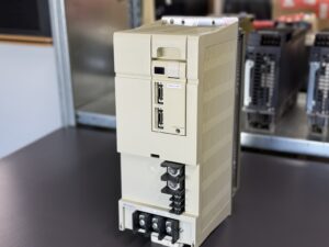
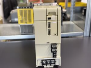
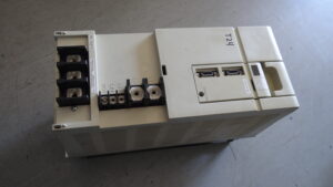
Mitsubishi MDS-C1-CV-300 Power Supply Unit – Preventive Overhaul of a CNC Power Supply During Scheduled Machine Rebuild
Introduction as a Real Service Case.
A long-running CNC machining center in a metal processing facility began showing sporadic alarm messages on a Mitsubishi MDS-C1-CV-300 power supply unit. The machine was still operating reliably, however irregular alarm events indicated early signs of aging within the power section.
Since there was no immediate production downtime, the customer deliberately decided against emergency repair and scheduled the overhaul preventively during a planned machine refurbishment. The goal was to avoid an unexpected production shutdown later.
The installed unit supplies several servo axes and the DC bus voltage for the drive system. The operational stability of this assembly is therefore critical for the complete machine.
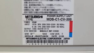
The nameplate confirmed the following configuration:
Mitsubishi Power Supply Unit MDS-C1-CV-300
30 kW output
3-phase input 200 to 230 V
Output 144 A DC 270 to 311 V
Manufacturing date 01/2006
The component structure included:
| Assembly | Designation |
|---|
| Control PCB | RK415B-2 |
| Power PCB | RK485B-300 |
| Capacitor PCB | RK494A-300 |
| Power section | Mitsubishi power module |
The information was taken directly from the uploaded manuals and images.
Initial Diagnosis
During incoming inspection, several typical aging symptoms of industrial power supply systems in this performance class were identified.
Visual inspection revealed:
- thermally stressed power sections
- aged DC bus capacitors
- discoloration near high-current traces
- increased oil and dust contamination in cooling areas
- aging power connector contacts
The alarm history was also analyzed. The customer reported occasional alarms without machine shutdown.
Particularly relevant were the following Mitsubishi alarm definitions:
| Alarm | Meaning |
|---|
| 69 | Ground fault |
| 6C | Main circuit error |
| 75 | Overvoltage |
| 77 | Power module overheat |
The official alarm definitions originate from the Mitsubishi documentation.
Measurements on the test bench showed no complete failure, however slight instability in the DC bus charging circuit and temperature-related fluctuations inside the power section were detected.
Actual Root Cause
The technical investigation revealed several interacting aging mechanisms.
Detected causes:
- reduced capacitance of DC bus capacitors
- increased ripple voltage inside the DC link
- thermally stressed RK485B-300 power PCB
- aging power connectors
- elevated thermal load on the power module
- unstable charging behavior in the DC bus circuit
- contaminated cooling channels with restricted airflow
The sporadic alarm condition was not caused by a single catastrophic defect but by the interaction of several aging-related issues.
The most critical potential developments were:
- Alarm 6C Main Circuit Error
- Alarm 75 Overvoltage
- Alarm 77 Power Module Overheat
According to Mitsubishi documentation, these alarms can eventually result in a complete machine shutdown.
Repair Process
The repair was carried out as a complete preventive overhaul of the power supply unit.
Performed work included:
- complete disassembly
- industrial cleaning of all PCBs
- replacement of aged electrolytic capacitors
- thermal rework of stressed solder joints
- inspection of power semiconductors
- gate driver verification
- heatsink cleaning
- replacement of thermally stressed connectors
- insulation testing
- ESR measurement of capacitors
- charging and discharge circuit verification
- load simulation tests
The unit was additionally tested for several hours under thermal stress conditions on our industrial load test bench.
Final Testing and Return Shipment
After completion of the overhaul, the Mitsubishi MDS-C1-CV-300 was tested extensively on an industrial test system.
Testing included:
- DC bus testing
- voltage stability under load
- simulated acceleration cycles
- thermal stress testing
- long-term runtime tests
- regenerative load simulation
- communication testing with connected drives
After overhaul, the power supply operated completely stable without recurring alarms.
The preventive repair strategy allowed the customer to use the planned maintenance window efficiently and avoid unexpected production downtime.
Customer Feedback
“The preventive overhaul was the right decision. The machine remained operational without emergency downtime and the power supply has been running perfectly stable ever since.”
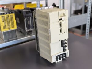
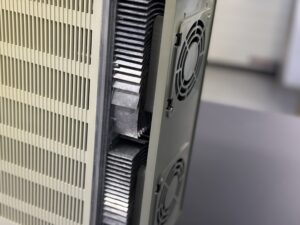
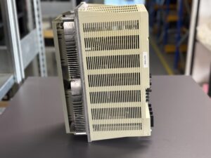
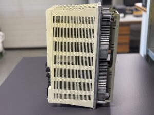
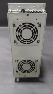
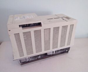
To mentioned Mitsubishi Drive: Mitsubishi Power Supply Unit MDS-C1-CV-300
More details about our Mitsubishi repair services can be found here:
Mitsubishi drive Repair by Industrypart
📞 Feel free to contact us with any questions about your Mitsubishi drive technology.
Our expert team is happy to help!
Technical Specifications
| Parameter | Value |
|---|
| Manufacturer | Mitsubishi Electric |
| Model | MDS-C1-CV-300 |
| Device Type | Power Supply Unit |
| Power | 30 kW |
| Input Voltage | 200 to 230 V AC |
| Input Phases | 3-phase |
| Frequency | 50/60 Hz |
| Input Current | 107 A |
| Output Voltage | DC 270 to 311 V |
| Output Current | 144 A |
| Hardware Version | C |
| Manufacturing Date | 01/2006 |
| Manual | BNP-C3000 |
Technical values from the nameplate and uploaded Mitsubishi documentation.
Operating Conditions
| Parameter | Specification |
|---|
| Ambient Temperature | 0 to 55 °C |
| Storage Temperature | -20 to +85 °C |
| Humidity | max. 90% non-condensing |
| Mounting | Electrical cabinet |
| Cooling | Forced air cooling |
| Protection Environment | Industrial environment |
Values from the uploaded technical documentation.
Cooperation with Other Equipment
The Mitsubishi MDS-C1-CV-300 typically operates together with:
- Mitsubishi MDS servo drives
- Mitsubishi MDS-D/DH axis amplifiers
- CNC controls
- spindle drives
- servo axes
- regenerative brake circuits
- encoder systems
- machine tool control systems
Compatible communication and power structures are described in the uploaded manuals.
Functional Description
The Mitsubishi MDS-C1-CV-300 provides the central energy supply for the CNC drive system.
Main functions include:
- DC bus voltage generation
- supply of multiple servo axes
- voltage stabilization
- regeneration management
- DC bus monitoring
- overcurrent and overvoltage protection
- thermal protection
- communication with servo and spindle amplifiers
The unit handles highly dynamic load changes typical for CNC machine tools.
Protection functions continuously monitor:
- input voltage
- DC bus voltage
- regenerative load
- temperature
- power module condition
- phase status
- communication status
Alarm and Error Codes
The uploaded Mitsubishi documentation shows two alarm indications for the power supply unit:
- the alarm number
- the LED segment display shown on the front panel
Example:
| Alarm Number | LED Display |
|---|
| 69 | 9 |
| 6C | C |
| 6E | E |
| 75 | L |
The alarm display table below follows the original Mitsubishi documentation exactly.
Mitsubishi MDS-C1-CV-300 Alarm Table
| Alarm No. | LED Display | Alarm Name | Meaning | Action |
|---|
| 69 | 9 | Ground Fault | Motor power cable connected to FG / ground fault | Check insulation of motor and power cables |
| 68 | 8 | Watchdog | Internal system malfunction | Check control PCB and power supply |
| 67 | 7 | Phase Failure | Missing input phase | Check incoming power |
| 6A | A | External Contactor Melting | Main contactor welded | Check and replace contactor |
| 6B | b | Rush Relay Error | Inrush relay malfunction | Check pre-charge circuit |
| 6C | C | Main Circuit Error | DC bus charging fault | Check capacitor charging path |
| 6D | d | Parameter Error | Incorrect parameter setting | Verify configuration |
| 6E | E | Memory Error | Internal memory failure | Check control electronics |
| 6F | F | Power Supply Error | Power supply or communication failure | Check supply voltages |
| 73 | J | Over Regeneration | Regenerative overload | Check braking resistor |
| 75 | L | Overvoltage | Excessive DC bus voltage | Check power supply and regeneration |
| 77 | n | Power Module Overheat | Thermal overload in power module | Check cooling system |
Alarm data originates from the uploaded Mitsubishi documentation.
Preventive Measures for the Customer
For industrial CNC power supply systems in this performance class, preventive maintenance is strongly recommended.
Recommended measures:
- regular cleaning of cooling paths
- cooling fan inspection
- ESR measurement of DC bus capacitors
- thermal imaging under load
- inspection of power terminals
- insulation testing of motor cables
- regeneration circuit testing
- tightening of power connections
- grounding inspection
Especially in high-dynamic CNC applications, preventive overhaul significantly extends operational lifetime and reduces the risk of unplanned downtime.
Conclusion
The preventive overhaul of the Mitsubishi MDS-C1-CV-300 allowed targeted repair before a critical failure occurred. Through technical analysis, replacement of aging components and extensive load testing, the operational reliability of the entire CNC system was significantly improved.