30.09.2026 by Viktor Siebert
Mitsubishi MDS-B-CVE-37 with No Function: Defective Power Stage and Driver Circuit
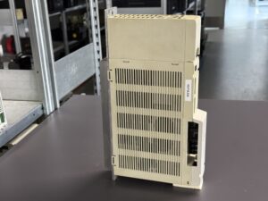
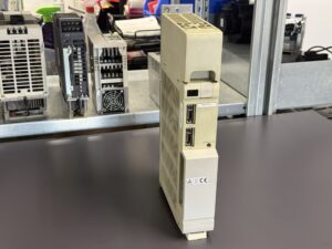
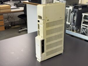
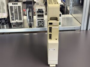
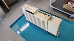
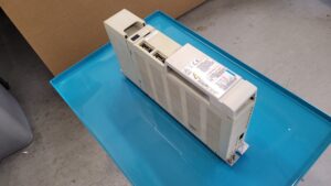
A Mitsubishi Power Supply Unit MDS-B-CVE-37 arrived at industrypart with a clear fault description: the unit had no function. Our inspection confirmed an internal power-stage fault. The transistor module and its driver circuit were affected. The cause was therefore located in the power section of the supply, rather than merely an externally visible connection or display issue.
Our technical assessment attributes the failure to component ageing. Potentially insufficient heat-sink cooling is another possible contributing factor. This does not, however, establish a confirmed fan failure or a measured overtemperature. That distinction matters when assessing the damage accurately.
What Does the Power Supply Unit Do?
The MDS-B-CVE-37 belongs to Mitsubishi drive technology for CNC machines. As a central supply unit, it provides electrical energy for the connected drive modules. It differs from a Servo Drive or Spindle Drive: the downstream drive modules perform the actual motor control.
The interaction between these assemblies explains why a central power supply fault can affect the availability of the entire associated drive system. Even if the connected motor is mechanically sound, its drive requires a working energy supply. A power supply fault should therefore not prematurely be classified as a motor fault.
The external similarity of two units is not enough to select replacement parts. The complete model designation, version, connections and specific machine configuration must match. This is particularly relevant to older MDS-B systems using different capacities and versions.
Incoming Fault: No Function
The reported condition on arrival was “no function”. No specific alarm number was supplied for this repair case. We therefore do not retrospectively assign an assumed alarm code to the incoming condition. Loss of function and a particular alarm message are different pieces of information.
Troubleshooting first needs to establish whether the external supply is missing or the unit has an internal fault. General checkpoints include the incoming supply, enables and connections, as well as internal supply and power circuits. In this case, inspection produced a specific internal finding: the transistor module and its driver circuit were defective.
Why the Power Module and Driver Circuit Are Considered Together
The transistor module forms part of the power stage. Its driver circuit ensures that the power semiconductors enter their intended switching states. Both areas are closely linked in operation. Looking only at the visibly damaged power component during diagnosis can leave another fault in its driver circuit undetected.
Assessing both areas together is therefore essential to a technically sound repair. This includes not just visible damage, but also the conditions under which the power module is driven. The general fault description alone does not identify the individual driver components or boards affected.
The documented finding clearly identifies the repair area. A detailed list of components actually replaced was not supplied for this report. We therefore do not list specific transistor types or a blanket replacement of capacitors, relays or optocouplers as completed work.
Component Ageing and Possible Thermal Stress
Electronic components change over their operating life. Their exposure depends on factors including operating hours, switching events and temperature. For this unit, ageing was assessed as the cause of failure. Insufficient heat dissipation could have increased thermal stress further.
Heat sinks can only fulfil their purpose if sufficient heat is transferred to the surroundings. Dirty cooling surfaces, restricted airflow or unfavourable cabinet temperatures are therefore useful checkpoints when investigating comparable damage. These general relationships do not replace evidence for the specific failure.
In particular, the finding does not establish that a fan definitely failed. Nor does it identify the temperature actually reached by a component. Checking the cooling conditions is nevertheless sensible for the operator, so that a repaired unit is not returned to unfavourable operating conditions.
Documentation and Test-Bench Inspection
The photographs and videos document the unit and its connection at the test bench. Such footage illustrates the test setup. It does not replace a measurement record covering output values, load or test duration. A particular test lasting several hours cannot be inferred from it.
The actual test conditions and results are essential to a complete final assessment. For a central power supply, these include its interaction with the connected drives and evaluation under the intended operating conditions. Details depend on the unit configuration and manufacturer requirements.
This report therefore keeps the confirmed incoming findings separate from the visible documentation. It does not claim successful reinstallation at the customer’s site or completed return shipping, as no information confirming these stages is available.
What Operators of Older Mitsubishi Drive Systems Should Watch For
Airflow paths and cooling surfaces should be checked regularly. The appropriate scope depends on the environment and operating load. Oil mist, dust and deposits inside the cabinet deserve particular attention. A universal maintenance interval cannot be set without knowing the installation.
Accurate fault documentation also helps: What indication appears on the power supply, what message appears on the spindle or servo drive, and under which operating conditions does the fault occur? Photographs of complete displays and unit designations help identify the technical context. A short description such as “no function” is a starting point, but does not replace diagnosis.
Work on power electronics and DC-link circuitry belongs in the hands of qualified specialists. Stored electrical energy can remain after switching off. Isolation and checks must follow the requirements specific to the unit and machine.
Technical Assessment of This Repair Case
The Mitsubishi MDS-B-CVE-37 illustrates why a complete loss of function calls for component-level examination. In this case, both the transistor module and its driver circuit were affected. Component ageing was assessed as the cause; potentially insufficient cooling remains an additional suspicion. The repair focus is therefore the combined assessment of the power module, its driver circuit and operating conditions.
Price, Lead Time and Further Information
Current information on the price and lead time of the Mitsubishi Power Supply Unit MDS-B-CVE-37 is available on the corresponding product page.
Further information about our repair services for Mitsubishi drive technology is available in the manufacturer section.
📞 Please feel free to contact us with questions about your Mitsubishi power supply or drive technology. Our team can assist with the technical assessment, repair and testing of your unit.
Technical Specifications
The unit is identified as MDS-B-CVE-37 from the information supplied. A matching original nameplate is unavailable. Specifications were researched in Mitsubishi manufacturer documentation.
| Feature | Technical information |
|---|
| Manufacturer | Mitsubishi Electric |
| Model | MDS-B-CVE-37 |
| Search spelling | MDSBCVE37 |
| Unit type | Power Supply Unit; central DC supply with regenerative function |
| Series | MDS-B |
| Capacity class | 3.7 kW; not 37 kW |
| Mains supply | Three-phase; manufacturer specifies 200 V at 50 Hz or 200–230 V at 60 Hz |
| Voltage tolerance | +10% / −15% according to series specification |
| Frequency | 50/60 Hz, tolerance ±3 Hz according to series specification |
| Output | DC link; BNP-C3015A specifies 270 V, while BNP-B3759B specifies 270–311 V for MDS-A/B-CV. These are not measurements taken on this unit. |
| Output current / input current | Not reliably established for this unit; no rated current calculated from power and voltage |
| Dimensions | Height × width × depth: 380 × 60 × 300 mm; type A1 |
| Weight | 5.0 kg according to model table |
| Cooling | Heat sink / airflow; specific fan type and condition not documented |
| Number of axes | No motor axis of its own; supplies a configured drive system |
| Production year / serial number | Not established |
| Documentation | Mitsubishi BNP-C3015A(ENG), I-5 and II-1 to II-6; additionally BNP-B3759B(ENG) |
Application Environment and Compatible Equipment
The unit supplies Mitsubishi CNC drive systems. Manufacturer manual BNP-C3015A includes combinations with MDS-B-SPT spindle drives. Permissible combinations depend on motor output, drive characteristics, total load and machine configuration. This does not establish universal interchangeability with MDS-C1-CV-37 or other CV variants.
Before replacement, verify the complete version, wiring, supply conditions, enables and machine-specific requirements. A seemingly suitable housing cover alone does not identify the power supply.
Functional Description
The unit provides a common DC link for the connected drive modules. The power circuit converts the incoming energy; the regeneration circuit forms part of the supply concept. Downstream drives perform the actual motor control. Direct motor encoder control is not the main function of this power supply.
The driver circuit, internal supply, charging functions, monitoring and enable signals work together. Failure of the power transistor or its driver can impair supply operation. Protective indications do not replace component-level diagnosis.
Components
The overview distinguishes confirmed fault areas, visible elements and general functional groups. Specific board or semiconductor part numbers have not been established.
| Assembly | Designation | Quantity | Function | Finding / classification |
|---|
| Transistor module | Part number not documented | Not documented | Power switching | Confirmed defective |
| Driver circuit | Board designation not documented | Not documented | Drives the power module | Confirmed defective |
| Heat sink / housing | Visible cooling and housing area | No parts list | Heat dissipation / protection | Cooling problem only suspected |
| Front display | LED display | 1 visible | Status and fault indication | No incoming alarm code confirmed |
| Front connectors | CN4, CN9 | 1 each visible | Unit connections | Verify function / pinout against the correct wiring diagram |
| Charging and DC-link circuit | General functional group | No parts list | DC-link charging and energy supply | No separate fault confirmed |
Alarm Messages and Troubleshooting
The table uses Mitsubishi documentation for the MDS-B power supply. The two-character code on the connected drive and the character on the Power Supply Unit are separate indications. This case arrived with “no function”, without a confirmed alarm code.
The final column provides general technical diagnostic approaches, not repair steps presented as verbatim manufacturer instructions. The uploaded single-page extract contains mostly the same basic codes, but differs in warning numbers and certain timing/reset details. Those details must not be mixed between document revisions.
| Drive code | Supply LED | Original name | Meaning | General diagnostic approach |
|---|
| 61 | 1 | Power module overcurrent | Overcurrent in power module | Examine the power stage, driver circuit and connected load together. |
| 63 | 3 | Auxiliary regeneration error | Auxiliary regeneration transistor remains on | Examine the auxiliary regeneration circuit and its driver. |
| 65 | 5 | Rush relay error | Precharge bypass relay fails to switch on | Check precharge circuit, relay and supply. |
| 67 | 7 | Open phase | Missing input phase | Check three-phase input and connections. |
| 68 | 8 | Watch dog | Internal execution watchdog triggered | Examine internal supply and control circuitry. |
| 69 | 9 | Ground fault | Motor ground fault; detected at READY ON | Test motor and cables correctly; do not automatically replace the supply. |
| 6A | A | External contactor melt | External contactor on despite READY OFF | Check contactor, feedback and control circuit. |
| 6B | b | Rush relay melting | Precharge bypass relay remains on | Examine relay and associated circuitry. |
| 6C | C | Main circuit error | Abnormal DC-link charging | Examine precharge and DC link for faults. |
| 6E | E | Memory error | Memory fault | Check controller and internal supply. |
| 6F | F | A/D converter error / Power supply error | A/D converter or supply fault | Check measurement circuitry and auxiliary supply. |
| 71 | H | Instantaneous stop | Supply interruption or external contactor drops out | Check input supply, contactor and enable chain. |
| 75 | L | Overvoltage | DC-link voltage above 410 V | Check mains conditions and regeneration. |
| 77 | n | Power module overheat | Power-module overheating | Check heat dissipation and ambient conditions. |
Warnings and Document Differences
The uploaded extract “ALARMS MDS_A-13.pdf”, page II-5, lists E0 / LED o and E1 / LED P. The researched BNP-C3015A, page II-6, lists corresponding warnings as E8 / o and E9 / p, with EA / q and EB / r additionally included. The extract alone therefore does not establish every detail for every MDS-B version. Timing limits and reset procedures must follow the documentation applicable to the actual unit and machine configuration.
Diagnostic Notes on the Main Fault
The confirmed findings are loss of function and defective transistor module and driver circuit. Neither alarm 61 nor 77 was reported for the incoming condition. The finding must therefore not automatically be renamed “overcurrent alarm” or “overtemperature alarm”.
In general, external supply and enable issues must first be distinguished from internal faults. Within the power stage, the module and driver should be assessed as an interconnected system. The exact replacement parts list, measurements and final test result have not yet been documented.
Preventive Measures
Regularly check heat sinks, airflow paths and cabinet conditions. Inspect worn fans and replace them as indicated by their condition. Have connectors and DC-link connections checked correctly. Record complete indications and operating conditions when intermittent faults occur. No fixed maintenance interval or completed preventive component replacement is claimed for this case.