25.08.2026 by Viktor Siebert
CNC Failure Under Load: Mitsubishi MDS-DM-V3-404040 with Alarm F1 32 Only After Extended Machining
The Mitsubishi MDS-DM-V3-404040, alternatively also referred to as MDSDMV3-404040, came to us with a particularly interesting fault pattern. During normal machine operation, initially no fault could be detected. The machine could start and operate. Only when the Servo Drive was actually subjected to load for a longer period did alarm F1 32 occur.
According to the customer, the fault typically appeared only after approximately half an hour of machining under load. As the operating time increased, the fault occurred more frequently. Faults like this are particularly difficult in practice because a short functional test can initially give the impression that the unit is operating perfectly.
In the Mitsubishi MDS-D/DH system, when an alarm occurs, the LED display alternately shows the axis number and the alarm number. Alarm 32 is described in the Mitsubishi manual as “Power module error (overcurrent)”. This means that the power module’s overcurrent protection function has been activated. Mitsubishi specifies PR as the reset method, meaning that the NC power supply must be switched on again. For a servo axis, a Dynamic Stop is performed.
The fact that the fault did not occur immediately after switching on, but only after prolonged operation under load, was particularly important for the diagnosis.
Initial Diagnosis in Our Workshop
With this type of fault pattern, it is not sufficient simply to switch on the Mitsubishi Servo Drive and let it run for a few minutes without any significant load.
In addition to a visual inspection, the initial examination therefore focused particularly on the areas that Mitsubishi specifies for alarm 32.
In the Mitsubishi troubleshooting documentation, the following checks are specified for alarm 32:
- Check the U, V and W motor power cables for short circuits and correct connections
- Check the insulation of the motor against ground
- Check the correct sizing and capacity of the Drive Unit
- Check the current control parameters
- Check the detector connectors
- Check the detector cable for connection faults
- Check whether the fault is reproducible
- If the fault occurs intermittently, also consider environmental influences such as temperature, electrical noise and grounding
If the fault can clearly be assigned to the Drive Unit, the Mitsubishi manual specifies replacement of the Drive Unit.
For a repair workshop, however, this is where the actual troubleshooting at assembly and component level begins.
Why the Fault Only Occurred After Approximately 30 Minutes
The customer’s description of the fault was extremely important for the diagnosis.
A completely failed power module would often become noticeable immediately after switching on, at Servo Ready, or directly when load is applied. In this case, however, the MDS-DM-V3-404040 initially operated normally.
Alarm F1 32 was only triggered after extended machining and the corresponding electrical and thermal load.
This indicated load-dependent or temperature-dependent fault behavior within the drive. This is a technical conclusion based on the observed repair case and not a direct statement from the manual.
Under prolonged load, the operating conditions inside the unit change. Power semiconductors, the DC bus, driver stages and other assemblies reach different temperatures than during a short functional test. Components whose electrical characteristics are already close to their limits may therefore still operate when cold and only become unstable after warming up.
For exactly this reason, this drive had to be tested not only statically, but also under realistic operating conditions.
Actual Fault Analysis
The fault analysis focused on the power electronics and their control circuitry.
The decisive factor was not alarm 32 alone, but the combination of:
- fault-free startup
- initially normal machine operation
- fault occurring only after extended machining
- correlation with increased load
- increasing frequency of the fault
- overcurrent indication from the power module
Mitsubishi alarm 32 confirms that the overcurrent protection function of the power module has been activated.
An important distinction must be made here: the alarm code describes the detected fault condition, but it does not automatically identify the individual defective electronic component.
It would therefore not be technically correct to conclude from alarm 32 alone that a specific IGBT, gate driver or individual capacitor is defective. Only an examination of the individual assemblies allows the actual fault to be narrowed down reliably.
Repair of the Mitsubishi MDS-DM-V3-404040
Following the initial diagnosis, the Servo Drive was disassembled and the individual assemblies were systematically checked.
According to our unit documentation, the MDS-DM-V3-404040 in this repair case consists of the following main assemblies:
| Assembly | Designation on PCB | Quantity | Function |
|---|
| Control board | RM115A-33 or BC886A028G51A | 1 | Control and signal processing |
| Power board | RM161B-444M or BN886A008G51A | 1 | Control and processing in the power section |
| Connection board | RM161B-444M or BC886A008G51A | 1 | Internal connection between assemblies |
| Power section | Power section | 1 | Power conversion for the connected axes |
During the repair, the relevant assemblies were not considered separately. Especially in the case of an intermittent overcurrent alarm, the interaction between the control electronics, driver circuitry and power section must be taken into account.
For this reason, after the actual repair, the unit was not subjected merely to a simple power-on test. The decisive stage was the subsequent test under load.
Load Testing as the Decisive Part of the Repair
An MDS-DM-V3-404040 with this type of fault can easily pass a short workshop test and still fail again after being installed in the machine.
According to the customer, the original fault window was approximately 30 minutes under load. The test therefore had to continue beyond this period.
Particular attention was paid to whether the behavior changed as the unit warmed up and whether alarm 32 occurred again.
Only when the Servo Drive operates reliably in a warm condition and under the corresponding load can a repair case of this type be considered properly completed.
For intermittent faults, this is one of the most important differences between a simple functional check and an actual repair test.
Final Test and Return Shipment
After completion of the repair, the Mitsubishi MDS-DM-V3-404040 was operated again on our test system.
The main points of the final test were:
- stable startup of the drive
- fault-free operation after warming up
- behavior under load
- monitoring of the power section
- observation over an extended operating period
- renewed testing for the original F1 32 fault pattern
The drive had to reach the same operating condition in which the fault had originally occurred at the customer’s machine.
Only after successfully completing the final test could the unit be released again for operation in the CNC machine and returned to the customer.
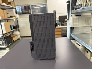
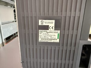
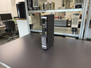
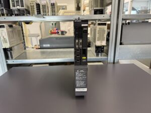
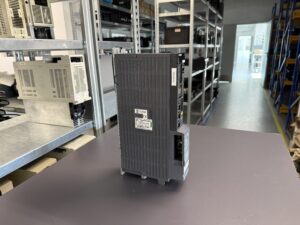
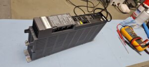
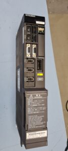
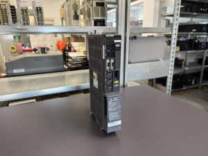
To mentioned Mitsubishi Drive: Mitsubishi Servo Drive Unit MDS-DM-V3-404040 or MDSDMV3-404040
More details about our Mitsubishi repair services can be found here:
Mitsubishi drive Repair by Industrypart
📞 Feel free to contact us with any questions about your Mitsubishi drive technology.
Our expert team is happy to help!
Technical Data Mitsubishi MDS-DM-V3-404040
The following values are taken directly from the nameplate of the unit in this repair case.
| Technical characteristic | Value |
|---|
| Manufacturer | Mitsubishi Electric Corporation |
| Device class | Servo Drive Unit |
| Type | MDSDMV3-404040 |
| Alternative designation | MDS-DM-V3-404040 |
| Power | 1.0 / 1.0 / 1.0 kW |
| Input | 21 A DC, 270 to 311 V |
| Control power supply | 0.2 A, 1 phase, 200 to 230 V AC |
| Control power frequency | 50/60 Hz |
| Output current | 7.8 / 7.8 / 8 A |
| Output | 3 phase, 155 V |
| Output frequency | 0 to 240 Hz |
| HW version | E |
| Country of manufacture | Made in Japan |
Information such as weight, protection class or software version that cannot be clearly determined from the available nameplate or documentation has intentionally not been added.
Operating Conditions
The documentation used for this case does not contain all specific environmental specifications for the MDS-DM-V3-404040. Therefore, no estimated temperature, humidity or altitude values have been added.
However, Mitsubishi’s troubleshooting documentation clearly states that environmental conditions should also be considered when investigating intermittent faults. Mitsubishi specifically mentions ambient temperature, electrical noise and grounding.
This is particularly important when dealing with a fault that only appears after an extended operating period.
Cooling of the electrical cabinet and the condition of the airflow paths are also important factors for power electronics. A fault that is not present when the unit is cold but only occurs after extended machining should therefore always be investigated from a thermal perspective as well.
Interaction with Other Devices
The MDS-DM-V3-404040 is designed as a multi-axis Servo Drive Unit within a Mitsubishi CNC drive system.
The three-channel power structure can already be identified from the nameplate information:
Power: 1.0 / 1.0 / 1.0 kW
Output Current: 7.8 / 7.8 / 8 A
A specific list of compatible motors, CNC controls or Power Supply Units cannot be reliably derived from the documentation available for this repair case and is therefore intentionally not added.
Functional Description
Within the CNC drive architecture, the Mitsubishi MDS-DM-V3-404040 provides controlled power to the connected servo motors.
The power electronics generate the required three-phase output for motor control from the supplied DC bus voltage. At the same time, the control electronics process commands and feedback signals and monitor the operating status of the system.
The protective functions of the MDS-D/DH system monitor, among other things:
- DC bus voltage
- overcurrent
- power modules
- regenerative circuit
- overtemperature
- motor overload
- motor temperature
- detector signals
- communication with the CNC
- communication between Drive Units
If a critical condition occurs, the corresponding alarm is generated and the axis is stopped according to the specified stop method.
Alarm F1 32 in Detail
On the unit in this repair case, F1 represents the axis assignment or axis indication in combination with alarm 32. According to Mitsubishi, the axis number and alarm number alternate on the LED display when an alarm occurs.
| Alarm | Fault name | Meaning | Reset | Action |
|---|
| F1 32 | Power module error (overcurrent) | The power module overcurrent protection function has been activated | PR | Check motor cable, insulation, capacity, parameters, detector and Drive Unit |
For alarm 32, Mitsubishi specifies Dynamic Stop as the servo stop method. For a spindle application, Coast to a stop is specified.
Additional Relevant Mitsubishi MDS-D/DH Alarm Codes
| Alarm | Fault name | Meaning | Reset |
|---|
| 10 | Insufficient voltage | Bus voltage in the main circuit is too low | PR |
| 17 | A/D converter error | Current feedback error detected | PR |
| 23 | Excessive speed error | Difference between actual and commanded speed is excessive | NR |
| 24 | Grounding | Motor power cable is in contact with FG | PR |
| 30 | Over regeneration | Regenerative load limit exceeded | PR |
| 31 | Overspeed | Motor exceeded the allowable speed | PR |
| 32 | Power module error (overcurrent) | Power module overcurrent detected | PR |
| 33 | Overvoltage | Main circuit bus voltage exceeded the allowable value | PR |
| 3A | Overcurrent | Excessive motor drive current detected | PR |
| 3B | Power module error (overheat) | Power module overheating detected | PR |
| 3C | Regeneration circuit error | Error in regenerative transistor or resistor | PR |
| 45 | Fan stop | Fan stopped and power module overheated | PR |
| 46 | Motor overheat / Thermal error | Thermal protection of motor or detector activated | NR |
| 50 | Overload 1 | Motor or Drive Unit overload level reached | NR |
| 51 | Overload 2 | Very high current command maintained for the defined period | NR |
The alarm designations and reset methods correspond to the Mitsubishi MDS-D/DH documentation.
What Mitsubishi Specifically Specifies for Troubleshooting Alarm 32
The troubleshooting section of the manual is particularly relevant to this repair case.
For alarm 32, Mitsubishi specifies a systematic procedure. First, the U, V and W power cables should be disconnected from the drive and motor and checked for short circuits and faulty connections.
The motor insulation against ground should then be checked. The manual specifies that an insulation resistance below 1 MΩ indicates a grounding fault and recommends replacement of the motor.
Further possible causes must then be checked:
- correct sizing of the Drive Unit
- correct axis assignment in multi-axis units
- current control parameters
- detector connector connections
- condition of the detector cable
- repeatability of the fault
- Drive Unit or detector as the source of the fault
- ambient temperature
- electrical noise
- grounding
If the fault is clearly located on the drive side, Mitsubishi specifies replacement of the Drive Unit as the corrective action.
The final part of Mitsubishi’s troubleshooting procedure is particularly relevant to this repair case. Alarm F1 32 did not occur immediately after power-up, but only after extended machining and corresponding load.
Why Alarm 32 Does Not Automatically Mean a Defective IGBT
In practice, when a Power module error or Overcurrent message appears, the power semiconductor module is often immediately suspected.
It can certainly be a possible source of the fault, but the alarm code alone does not prove this.
In the troubleshooting procedure for alarm 32, Mitsubishi explicitly includes external and system-related causes such as the motor cable, motor insulation, detector connection, parameter settings and environmental conditions.
With an intermittent alarm, it is therefore necessary first to determine whether the overcurrent is actually being caused by the power module itself or whether the drive is correctly responding to a critical condition elsewhere in the connected system.
Only after these points have been excluded or checked does targeted repair at assembly level make technical sense.
Preventive Measures for the Operator
With older Mitsubishi CNC Servo Drives, action should not only be taken once an alarm becomes permanent.
Regular inspection of the cooling system and electrical cabinet is particularly useful. Fans and airflow paths should remain clear. Connectors and power cables should be checked for secure connection, contamination and signs of thermal stress.
Motor cables and their insulation should also be considered when recurring overcurrent or grounding alarms occur.
For intermittent faults, it is also important to document the exact circumstances:
- After how much operating time does the fault occur?
- Does it only occur during machining?
- Is a specific axis affected?
- Does the fault occur during acceleration or deceleration?
- Does the frequency increase when the machine is warm?
- Which alarm number is displayed directly on the drive?
- Are there any additional alarms in the Mitsubishi drive system?
This information can significantly accelerate subsequent troubleshooting.
Conclusion
The repair case involving the Mitsubishi MDS-DM-V3-404040, also written as MDSDMV3-404040 AC Servo Drive Unit, clearly demonstrates why intermittent faults in CNC drive systems require sufficiently long testing.
Alarm F1 32 did not occur immediately at the customer’s machine. The drive only began to fail after approximately 30 minutes of machining under load. As the operating time increased, the fault occurred more frequently.
The Mitsubishi manual clearly defines alarm 32 as Power module error (overcurrent). The overcurrent protection function of the power module has been activated.
The decisive point during the repair was therefore not whether the unit could be switched on or operate without a fault for a few minutes. What mattered was whether it remained stable after warming up and under load.
A short functional test might not have revealed this fault pattern at all.
With temperature-dependent and load-dependent faults in particular, realistic load testing is therefore essential to determine whether the actual cause has been eliminated and whether the Servo Drive can once again operate reliably in the CNC machine.