06.05.2026 by Viktor Siebert
Repair of a Mitsubishi MDS-DH-SP-100 Spindle Drive Unit with Alarm 33 Overvoltage
Initial Situation and Fault Description.
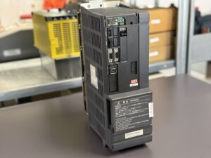
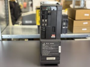
The Mitsubishi MDS-DH-SP-100 spindle drive unit was delivered with fault Alarm 33 Overvoltage. The error did not occur immediately after power-up but appeared intermittently during machining operations. It was particularly noticeable that the fault was independent of temperature or mechanical influence. Neither vibrations nor thermal load had a direct impact on the failure behavior.
The machine initially operated normally until a sudden stop occurred under load or during dynamic conditions. This type of fault typically indicates excessive DC bus voltage, where the intermediate circuit voltage exceeds permissible limits. This usually points to issues in the regeneration circuit or the power stage.
Incoming Inspection and Initial Diagnosis
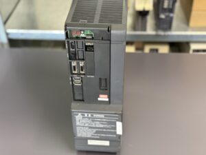
During incoming inspection, a visual check was performed first. No obvious external damage was detected. Connectors, cooling system, and housing appeared intact.
Electrical checks of the DC bus revealed unstable behavior under load simulation. Voltage levels were partially outside the expected range. Initial measurements indicated that regenerative energy was not properly dissipated.
External causes such as braking resistor or supply voltage were also checked and ruled out.
Technical Analysis
Alarm 33 indicates that the DC bus voltage exceeded the allowable level in the main circuit . Normally, this energy is dissipated through the regeneration circuit during deceleration.
In this case, a typical aging effect in the power stage was identified. The power section showed significant wear. Several power components were no longer operating reliably, and the control circuitry was also near its operational limits.
The cause-effect chain can be described as follows:
Aging of power electronics
→ unstable switching behavior in the power stage
→ insufficient energy dissipation
→ rise in DC bus voltage
→ Overvoltage alarm 33
A key aspect here is that such damage does not immediately lead to total failure. The drive continues to operate but becomes sensitive to load changes and dynamic processes. This explains the intermittent fault during machining.
Repair Measures and Refurbishment
The unit was completely disassembled and cleaned. The main focus was on the power stage and its control circuitry.
The following work was carried out:
Full disassembly and cleaning of all assemblies
Load testing of the power stage
Replacement of aged and critical power components
Reconditioning of the power stage control circuitry
Inspection of DC bus structure and energy paths
Replacement of thermally stressed components
Preventive measures were also implemented, especially regarding thermal stability and long-term reliability.
Final Functional Test
After repair, the drive was tested on a test bench.
Test conditions:
Simulation of real spindle loads
Multiple start-stop cycles
Low speed operation
Medium speed ranges
High speed with dynamic load changes
Special attention was given to:
DC bus voltage behavior
Power stage stability
Response during load changes
Control signal stability
The system operated stable across all operating conditions. The overvoltage fault did not reoccur.
Conclusion
The failure was caused by an aged and unstable power stage. Such faults are typical because they do not appear immediately but only under dynamic load conditions.
By fully refurbishing the power stage, long-term functionality was restored. The repair is sustainable because not only the immediate fault was corrected, but also critical components were replaced preventively.
More details about our Mitsubishi repair services can be found here:
Mitsubishi drive Repair by Industrypart
📞 Feel free to contact us with any questions about your Mitsubishi drive technology.
Our expert team is happy to help!
Technical Specifications
| Parameter | Value |
|---|
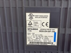
| Manufacturer | Mitsubishi Electric |
| Device Type | Spindle Drive Unit |
| Model | MDS-DH-SP-100 |
| Series | MDS-D/DH |
| Power | approx. 15 kW |
| Input Voltage | 380–480 V AC / DC 513–648 V |
| Output Voltage | approx. 340 V |
| Rated Current | approx. 30 A |
| Control Type | Vector control |
| Feedback | Encoder (motor-side) |
| Cooling | Fan cooled |
| Protection Class | IP20 |
| Ambient Temperature | 0 to approx. 55 °C |
| Mounting | Control cabinet |
| Origin | Japan |
| Product Status | Discontinued |
Application Environment and Use Cases
Typical machines include CNC machine tools, turning centers, and milling machines.
Typical production years range from approximately 2000 to 2010.
Applications include spindle drives with high dynamics and varying load conditions.
Stable power supply, proper grounding, and sufficient cooling inside the control cabinet are essential. Rapid deceleration with high regenerative energy is particularly critical.
Functional Description
The spindle drive converts input voltage into a controlled DC bus voltage and generates motor currents.
The power stage drives the motor, while the control system compares setpoint and actual values. Feedback is provided via encoder.
The protection logic monitors:
DC bus voltage
Current
Temperature
Communication
If limits are exceeded, the system stops.
These functions are safety-critical, as they protect both the motor and the machine.
Alarm Messages and Troubleshooting
| Alarm Code | Description | Possible Cause | Recommended Action |
|---|
| 10 | Undervoltage | Power supply issue | Check supply |
| 17 | A/D error | Feedback issue | Check electronics |
| 23 | Speed deviation | Control issue | Check parameters |
| 30 | Over regeneration | Brake resistor overload | Check resistor |
| 31 | Overspeed | Control issue | Check parameters |
| 32 | Overcurrent | Power stage issue | Check motor/drive |
| 33 | Overvoltage | DC bus too high | Check regeneration/power stage |
| 3A | Overcurrent | Load issue | Check mechanics |
| 3B | Overtemperature | Cooling issue | Check fan |
| 46 | Motor overheat | Overload | Reduce load |
Assembly Overview
| Type | Designation on Board | Quantity |
|---|
| Control board | RM111C-21 or BN638A503G51 | 1 |
| Power board | RM165C-SP-M or BC886A021G51 B | 1 |
| Power unit | BKO-NC1208 H88 or MR08-DH-SP-100 (uncertain, verify if needed) | 1 |
Safety Notice
Before opening or disconnecting connectors, always switch off power, secure against reconnection, wait for discharge time, and verify absence of voltage.
Measurements on live components may only be performed by qualified personnel using appropriate equipment and in accordance with local regulations.