09.10.2026 by Viktor Siebert
Mitsubishi MDS-D2-V3-202020: F1/32 alarm and power-stage failure
F1/32, failed transistor modules and faulty drive circuitry: A Mitsubishi MDS-D2-V3-202020 Servo Drive Unit arrived at industrypart for investigation. Alongside the damaged power stage, measurements revealed drive-circuit abnormalities at the other two transistor modules. A heavily contaminated fan provided an important clue to a possible cause: it still rotated, but our workshop assessment found insufficient airflow for adequate cooling.
Documented unit data
The following electrical ratings were transcribed from the supplied nameplate photograph. MDS-D2-V3-202020 and MDSD2V3-202020 are the two model spellings used for the unit documented here.
| Item | Details |
|---|
| Manufacturer / series | Mitsubishi Electric / MDS-D2 |
| Model | MDS-D2-V3-202020; nameplate: MDSD2V3-202020 |
| Product type | Servo Drive Unit |
| Nameplate power | 1.0 / 1.0 / 1.0 kW |
| Main circuit input | 21 A; DC 270–311 V |
| Additional nameplate input | 0.2 A; 1PH 200/200–230 V; 50/60 Hz |
| Output | 4.6 / 4.6 / 4.6 A; 3PH 155 V; 0–240 Hz |
| Protection rating | IP20 |
| Nameplate date | 2018-05 |
| Hardware / software | J / 1501W101 A8 |
| Manual reference on nameplate | IB-1501124 |
Documented assemblies
| Assembly | Marking | Quantity |
|---|
| Control board | RM120B-33 / BC886A097G51A | 1 |
| Power board | RM161B-222D2 / BC886A008G51B | 1 |
| Interconnection board | RM161A1-2-MV3-222 / BN638A436G51A | 1 |
| Power section | – | 1 |
These markings come from the supplied component list. They identify assemblies and do not establish which replacement parts were fitted.
Reported fault on arrival
The unit arrived with the reported alarm indication F1/32. Diagnosis required comparing that indication with the actual condition of the assemblies. An alarm code identifies a detected fault condition; it does not replace inspection of the power modules, their drive circuitry and the cooling system.
Technical findings in our workshop
| Area | Confirmed finding |
|---|
| Power output stage | Defective; transistor modules had failed. |
| Drive circuitry of the failed modules | Faulty operation identified. |
| Drive circuitry of the other two transistor modules | Measurable abnormalities were already present. |
| Cooling | A heavily contaminated fan still operated but delivered insufficient airflow. |
The findings therefore extended beyond the visibly failed power components. Their associated drive circuits also needed to be assessed. Replacing only the failed modules would not resolve the problems already measurable in the remaining drive circuitry.
How the power stage, drive circuitry and cooling work together
The power output stage switches current for the connected servo motor. Its drive circuitry turns the power transistors on and off at the required times. Faults in this circuitry can impair switching and place additional stress on the power components.
Heat generated during operation must be removed through the intended cooling surfaces and airflow. Insufficient cooling increases thermal stress. For this reason, the power stage, drive circuitry and fans should be considered together when investigating this type of damage.
Why a rotating fan may still provide inadequate cooling
One fan in this unit was heavily contaminated. Although it still rotated, our assessment found that its airflow was no longer sufficient. A rotating fan does not, by itself, establish that cooling is adequate.
Restricted cooling is a plausible explanation for increased thermal stress and the subsequent power-stage failure. This assessment is based on the workshop findings; a recorded temperature history is not available. The nameplate date of 2018-05 alone does not establish operating hours, contamination or thermal loading.
Understanding F1/32
In the alternating LED display, F1 identifies axis 1 and 32 is the alarm number. Mitsubishi defines alarm 32 as an overcurrent indication from the power module. This indication alone does not prove fan contamination or overheating. In this case, the failed transistor modules and inadequate cooling were identified during the investigation.
Alarm list for the Mitsubishi MDS-D2/DH2 series
This selection helps distinguish indications relating to supply voltage, the power stage, cooling and loading. F1/32 was reported in this case. The other codes are reference information, not additional faults recorded for this unit.
| Alarm code | Meaning in the series manual |
|---|
| 10 | Insufficient DC bus voltage |
| 12 | Hardware error during power-on self-check |
| 17 | Current feedback / A-D conversion error |
| 24 | Motor power cable ground fault |
| 25 | Encoder absolute-position data lost |
| 30 | Regenerative resistor overload |
| 31 | Motor overspeed |
| 32 | Power module detects overcurrent |
| 33 | DC bus overvoltage |
| 3A | Excessive motor drive current detected |
| 3B | Power module detects overheating |
| 45 | Power-module overheating while the cooling fan is stopped |
| 46 | Motor/encoder overheating or thermistor-circuit fault |
| 50 | Overload 1: overload detection threshold reached |
| 51 | Overload 2: sustained very high current command |
| 52 | Excessive position following error during servo ON |
| 53 | Excessive position following error during servo OFF |
Fan and overload warnings
| Warning code | Meaning |
|---|
| A6 | A cooling fan in the drive unit has stopped. |
| E1 | Overload detection has reached 80% of the condition for alarm 50. |
A contaminated fan may still rotate while delivering insufficient airflow. The absence of a fan-stop warning therefore does not establish adequate cooling. Alarm 32 must also be distinguished from overheating alarms 3B and 45.
Source: Mitsubishi MDS-D2/DH2 Instruction Manual, IB-1501127-C, section 7.1.1, p. 385; alarm list 7.2.1, pp. 386–388; warnings 7.2.2, p. 391. This table is a selection from the series manual, not a complete list of all encoder, power-supply and special-function indications.
Preventive maintenance instead of unplanned downtime
This case illustrates why we have long recommended regular fan inspections, professional cleaning and timely fan replacement. Inspection should cover contamination, clear airflow paths, fan condition and actual cooling performance. Inspection and replacement intervals depend on manufacturer instructions and operating conditions.
A planned preventive overhaul can be more economical than power-stage damage followed by machine downtime. A breakdown may involve troubleshooting, removal, transport and recommissioning in addition to the repair. Detecting developing faults early allows them to be addressed during a planned maintenance stop.
Workshop case video
The video explains the power-stage findings and the role of inadequate cooling. Photographs of the unit and footage from the test bench complement the documentation.
Photo gallery
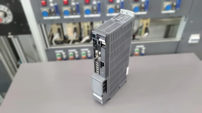 Mitsubishi MDS-D2-V3-202020 in an angled overall view at the test bench
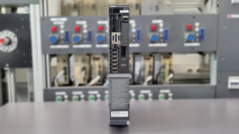 Front view of Mitsubishi MDS-D2-V3-202020 and its connectors
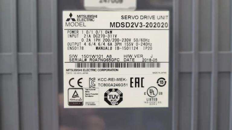 MDSD2V3-202020 nameplate with electrical ratings and date 2018-05
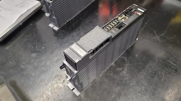 Mitsubishi MDS-D2-V3-202020 before repair on the workshop bench
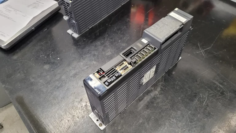 Angled view of Mitsubishi MDS-D2-V3-202020 before repair
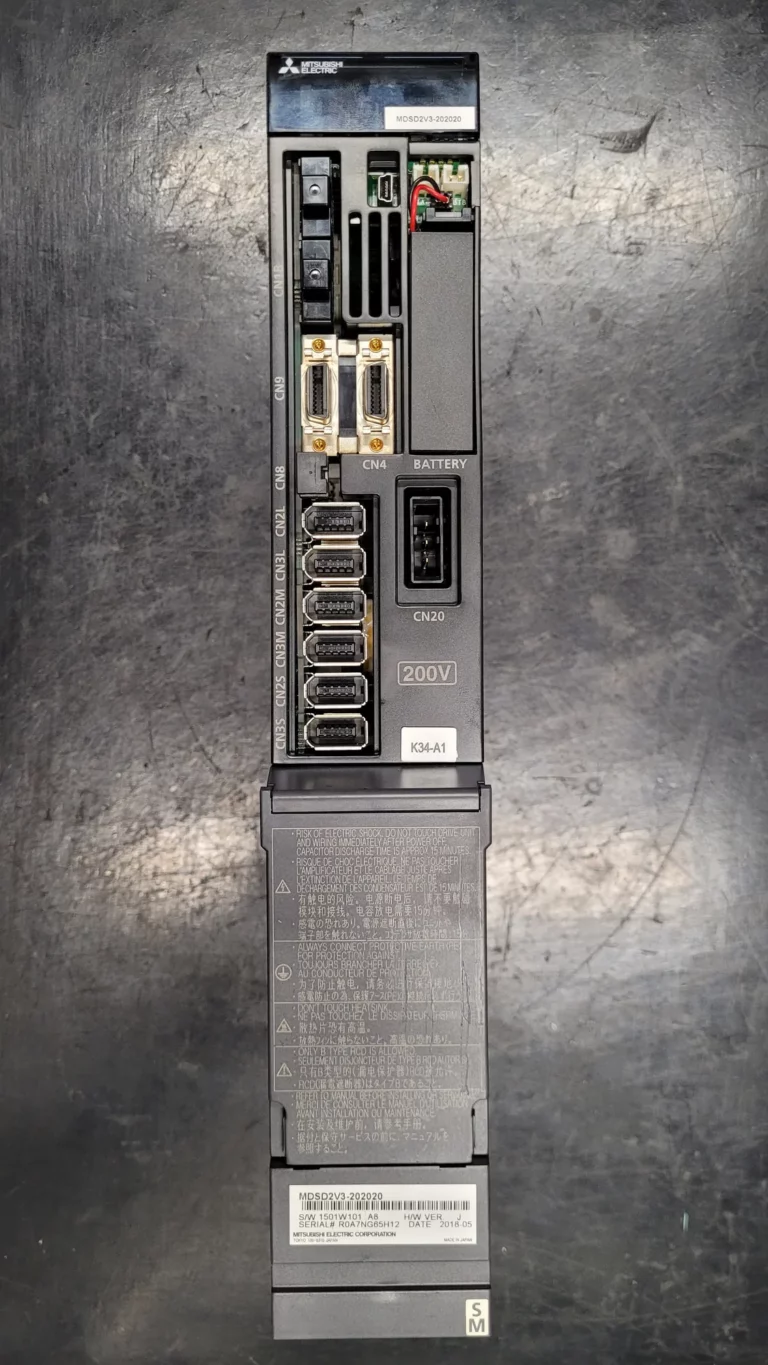 Front of Mitsubishi MDS-D2-V3-202020 before repair
Enquire about repair of your MDS-D2-V3-202020
Does your Mitsubishi MDS-D2-V3-202020 Servo Drive Unit display F1/32 or another fault? Send us the complete model designation, a nameplate photograph and the displayed alarm sequence. Describe whether the fault occurs at power-on, when the drive is enabled or during operation. Information about fan condition, contamination and previous maintenance also helps with the assessment.
industrypart supports you with diagnosis, repair and preventive overhaul of industrial drive electronics.
View the Mitsubishi MDS-D2-V3-202020 Servo Drive Unit in our shop.
For more information about our repairs of Mitsubishi servo and spindle drives, visit our Mitsubishi repair service page.