01.07.2026 by Viktor Siebert
Mitsubishi MDS-D2-CV-110 Power Supply Unit. Intermittent Voltage Drop Triggered S04 “Power Supply: Instant Power Interrupt”
An Unexpected Machine Shutdown During Spindle Operation
An industrial customer contacted our repair facility after a recurring and difficult-to-diagnose fault appeared on a CNC machine. The machine powered up normally and initially operated without any noticeable issues while idling. However, as soon as the spindle speed exceeded approximately 1,000 rpm, the machining process stopped abruptly.
The CNC control reported the following fault:
S04 – Power Supply: Instant Power Interrupt
The alarm did not occur immediately after power-up but only while the spindle was operating under load. This made troubleshooting particularly challenging. Because the fault appeared only during increased power demand, it posed a significant risk of unexpected machine downtime and production interruptions.
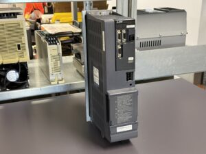
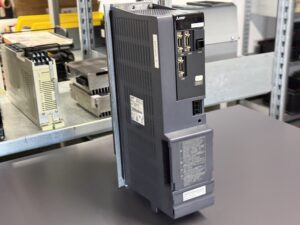
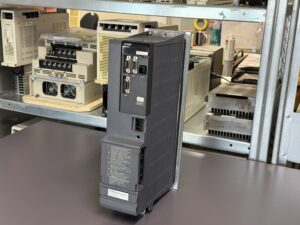
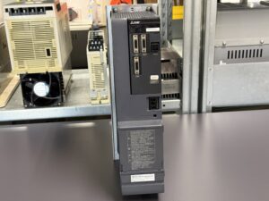
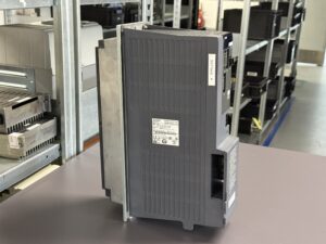
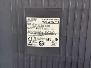
The unit sent to our workshop was a Mitsubishi Electric MDS-D2-CV-110 Power Supply Unit, responsible for supplying the connected servo and spindle drives within the Mitsubishi MDS-D2 system. According to the nameplate, the unit is rated at 7.5 kW, operates from a three-phase 200–230 VAC input, and provides a 270–311 VDC DC bus output. The hardware version was B, with a manufacturing date of October 2018.
Initial Diagnosis in Our Workshop
After arrival, the unit underwent our standard incoming inspection.
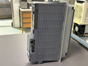
Externally, the power supply unit showed no visible signs of damage. There were no burned components, mechanical damage or excessive contamination.
The unit was then connected to our in-house test bench.
During the first functional tests, the customer’s fault description could be reproduced.
- Unit powered up normally
- Supply voltages initially remained stable
- No abnormalities during idle operation
- Fault reproducible only once spindle speed increased
- Alarm S04 appeared exclusively under higher load conditions
This behavior is typical of failures that only become visible under dynamic load. While the unit may still operate normally without load, voltage instability or power stage failures often become apparent only when higher current demand is present.
Root Cause Analysis
Following a detailed analysis of the power section, the actual cause of the failure was identified.
The investigation revealed:
- Failure within the power stage of the power supply unit
- DC bus instability under load
- Temporary collapse of the internal control power supply during high power demand
- Activation of the protection function against instantaneous power interruption
According to the Mitsubishi service manual, Power Supply Alarm 71 – Instantaneous Power Interruption indicates a momentary interruption of the power supply. Mitsubishi recommends checking the incoming power supply, wiring, contactors, voltage drops and, if necessary, the power supply unit itself.
Since all external causes could be excluded and the fault was consistently reproduced on our test bench, the internal power stage was confirmed as the root cause.
Repair Measures
After completing the diagnosis, the power supply unit was fully repaired.
The repair included:
- Repair of the power stage
- Replacement of defective electronic components within the power section
- Preventive replacement of aging components
- Inspection of the DC bus circuitry
- Verification of solder joints in the power section
- Complete cleaning of all assemblies
- Inspection of all connectors
- Verification of the cooling system
- Visual inspection of all printed circuit boards
- Complete electrical final inspection
In addition to repairing the actual fault, the entire unit received a preventive overhaul to improve long-term operational reliability.
Industrial power supply units often fail gradually. Years of thermal stress, repeated inrush currents and continuous operation cause individual components to deteriorate long before a complete failure occurs.
For this reason, our repairs do not focus solely on the failed component but on the overall condition of the entire assembly.
Final Testing on Our Test Bench
After completing all repair work, the Mitsubishi MDS-D2-CV-110 Power Supply Unit underwent comprehensive testing on our in-house test system.
The following functions were verified:
- Stable power-up behavior
- DC bus supply stability
- Performance under increasing load
- Operation during simulated spindle load
- Long-term thermal endurance test
- Verification of all protection functions
Special attention was given to the originally reported fault.
Even during repeated load cycles above 1,000 rpm, the alarm no longer occurred. The power supply remained completely stable throughout the entire test period.
After successfully passing all functional tests, the unit was approved for return shipment.
To mentioned Mitsubishi Drive: Mitsubishi MDS-D2-CV-110 Power Supply Unit
More details about our Mitsubishi repair services can be found here:
Mitsubishi drive Repair by Industrypart
📞 Feel free to contact us with any questions about your Mitsubishi drive technology.
Our expert team is happy to help!
Technical Specifications
| Specification | Description |
|---|
| Manufacturer | Mitsubishi Electric |
| Model | MDS-D2-CV-110 |
| Device Type | Power Supply Unit |
| Rated Power | 7.5 kW |
| Input Voltage | Three-phase 200–230 VAC |
| Input Current | 35 A |
| Frequency | 50/60 Hz |
| Control Supply | 200–230 VAC, 0.2 A |
| DC Bus Output | 270–311 VDC |
| Output Current | 41 A |
| Protection Class | IP20 |
| Hardware Version | B |
| Software Version | 1501W113 A6 |
| Manufacturing Date | October 2018 |
| Manual Reference | IB-1501124 |
Operating Conditions
| Parameter | Specification |
|---|
| Application | CNC machine tools |
| Supply Voltage | Three-phase 200–230 VAC |
| DC Bus | 270–311 VDC |
| Protection Rating | IP20 |
| Installation | Electrical control cabinet |
| Cooling | Forced air cooling |
| Operating Environment | Industrial environment according to Mitsubishi specifications |
Integration with Other Equipment
The Mitsubishi MDS-D2-CV-110 Power Supply Unit provides the central power supply for several components within the Mitsubishi MDS-D2 drive system.
Typical combinations include:
- Mitsubishi MDS-D2 Servo Drives
- Mitsubishi MDS-D2 Spindle Drives
- Mitsubishi CNC controls
- Servo axes
- Spindle drive systems
- Integrated DC bus supply via L+/L− according to the MDS-D2 system architecture.
Functional Description
The Mitsubishi MDS-D2-CV-110 serves as the central power supply for the complete MDS drive system. After receiving the incoming three-phase AC voltage, the unit rectifies the supply and stores the energy in the DC bus. This DC bus then supplies the connected servo and spindle drives with the required operating voltage.
In addition, the power supply continuously monitors numerous protective functions, including overcurrent, voltage monitoring, cooling fan supervision, phase loss detection, regenerative energy management and instantaneous power interruptions. Whenever an abnormal operating condition is detected, the unit generates the corresponding alarm to protect connected servo axes and spindle drives from consequential damage.
Power Supply Unit Alarm Table (Mitsubishi MDS-D2-CV-110)
| LED Display | Internal Alarm No. | Alarm Name | Description | Recommended Action |
|---|
| 61 | 1 | Power Module Overcurrent | The overcurrent protection of the power module has been activated. | Inspect the power stage, motor, power cables, and connected load. |
| 62 | 2 | Frequency Error | The input power supply frequency is outside the specified operating range. | Check the incoming power supply and power quality. |
| 66 | 6 | Process Error | An internal processing error has occurred within the power supply unit. | Inspect the electronics and check for environmental influences. |
| 67 | 7 | Phase Interruption | An input phase loss has been detected. | Verify the incoming power supply and wiring. |
| 68 | 8 | Watchdog | Internal system error detected in the power supply unit. | Inspect or replace the power supply unit if necessary. |
| 69 | 9 | Grounding | A ground fault between the motor power cable and protective earth (FG) has been detected. | Check motor insulation, power cables, and grounding. |
| 6A | 10 | External Contactor Welding | The external contactor contacts are welded or defective. | Inspect or replace the contactor and verify the control circuit. |
| 6B | 11 | Rush Circuit Error | A fault has been detected in the inrush current limiting circuit. | Inspect the inrush circuit and the main power circuit. |
| 6C | 12 | Main Circuit Error | An error occurred while charging the DC bus capacitor. | Check the main circuit and DC bus charging components. |
| 6D | 13 | Parameter Setting Error | An invalid parameter setting has been detected. | Verify parameter settings and communication with the drive units. |
| 6E | 14 | Memory / A/D Error | A memory, A/D converter, or unit identification error has been detected. | Inspect the internal electronics of the power supply unit. |
| 6F | 15 | Power Supply Error | Communication with the power supply unit failed or no power supply unit was detected. | Check communication wiring and the power supply unit. |
| 70 | 16 | External Emergency Stop Error | The external emergency stop signal does not match the NC emergency stop signal. | Verify the emergency stop wiring and control circuit. |
| 71 | 17 | Instantaneous Power Interruption | A temporary interruption of the power supply has been detected. | Check the incoming power supply, wiring, contactors, and the power supply unit itself. |
| 72 | 18 | Fan Stop | The cooling fan has stopped and the power module has overheated. | Inspect or replace the cooling fan and check the cooling system. |
| 73 | 19 | Over Regeneration | The regenerative resistor has exceeded its allowable load. | Inspect the regenerative resistor and braking circuit. |
| 75 | 20 | Overvoltage | The DC bus voltage has exceeded the allowable limit. | Check the incoming supply voltage and regenerative circuit. |
| 76 | 21 | External Emergency Stop Setting Error | Incorrect emergency stop switch setting or invalid emergency stop input. | Verify switch settings and emergency stop wiring. |
| 77 | 22 | Power Module Overheat | Thermal protection of the power module has been activated. | Inspect the cooling system, fan operation, and operating load. |
Components of the Mitsubishi MDS-D2-CV-110 Power Supply Unit
The Mitsubishi MDS-D2-CV-110 Power Supply Unit consists of only a few, yet highly critical assemblies that together provide the power supply for the entire MDS-D2 drive system. Each assembly performs a specific function and is individually inspected and evaluated during our repair process.
| Assembly | Board Designation | Function | Inspection / Repair Notes |
|---|
| Control Board | RM411C or BC886A091G51B | Monitors the power supply unit, communicates with the connected drive units, controls the protection functions, and supervises all internal operating conditions. | Inspection of the internal power supply, communication signals, protection circuits, and aging electronic components. |
| Power Board | RM463B-2 or BC886A096G51A | Contains the power electronics responsible for AC rectification, DC bus generation, and power distribution within the power supply unit. | Inspection of power semiconductors, current paths, solder joints, and thermally stressed components. In this repair case, the root cause of the failure was located on this board. |
| Power Module | D2-CV-110 | Central power conversion stage of the Mitsubishi MDS-D2 system. Converts the incoming AC supply into the required DC bus voltage for the connected servo and spindle drives. The module also continuously monitors numerous protection functions, including overcurrent, overvoltage, regenerative energy, and instantaneous power interruption. | Load testing under realistic operating conditions, verification of DC bus stability, and complete functional testing of all protection features after repair. |
Conclusion
This repair case clearly demonstrates that failures in industrial power supply units often become visible only under real operating load. Although the unit appeared to function normally while idling, increasing spindle load caused a temporary collapse of the internal supply voltage, triggering the S04 – Power Supply: Instant Power Interrupt alarm.
By repairing the defective power stage, performing a complete preventive overhaul and carrying out extensive load testing, the Mitsubishi MDS-D2-CV-110 Power Supply Unit was successfully restored to full operating condition. The unit is now ready to provide reliable service once again in the customer’s production environment.