20.10.2026 by Viktor Siebert
Mitsubishi MDS-D-V3-202020: Replacement prepared for Citizen L7-20
Three axes failed at the same time: a Citizen L7-20 was affected by a failure of its Mitsubishi MDS-D-V3-202020 Servo Drive Unit. Examination of the original unit revealed control PCB damage so severe that an economically sound, reliable repair was no longer possible. industrypart therefore sourced a suitable replacement unit, thoroughly inspected and overhauled it, and prepared it for the machine-specific requirements. The unit has since been installed at the customer’s site and is running.
Technical data and identification
The electrical values below come from the photographed nameplate of the original unit. The replacement photographs show a different physical unit. Software markings on the original nameplate therefore do not establish the final software configuration of the prepared replacement.
| Item | Documented value |
|---|
| Manufacturer / unit | Mitsubishi Electric / Servo Drive Unit |
| Model designations | MDSDV3-202020 / MDS-D-V3-202020 |
| Axes in this case | X, Y, Z / Citizen L7-20 |
| Nameplate power | 1.0 / 1.0 / 1.0 kW |
| Nameplate DC input | 21 A / DC 270–311 V |
| Separate nameplate AC input | 0.2 A / 1 PH / 200 V at 50 Hz, 200–230 V at 60 Hz |
| Nameplate output | 4.6 / 4.6 / 4.6 A / 3 PH / 155 V / 0–240 Hz |
| Original unit hardware revision | F |
| Original unit software marking | 1501W001 A5 |
| Manual reference on nameplate | IB-1500010 |
| Standard stated on nameplate | EN 50178 |
The three power and current figures relate to the three axis channels. The designation “202020” must not be interpreted as 20 kW continuous power or 20 A continuous current per axis. These are nameplate values, not measurements taken from the video. The DC input and separate single-phase AC input serve different functions and must not be treated as the same supply. EN 50178 is a standard reference, not an IP protection rating.
How does a three-axis servo drive work?
The power electronics convert energy from the DC link into controlled three-phase motor currents. The individual axis channels supply the connected servo motors according to the control system’s requirements. Feedback signals provide the information required for controlled motion and monitoring. Commands, operating states and faults are exchanged through communication with the CNC.
A multi-axis unit contains both axis-specific functions and shared electronics and supply paths. A shared fault can therefore stop several axes simultaneously. This is an important distinction from three independently failed motors. The precise distribution of control loops between the CNC and the drive depends on the system configuration.
Functional assemblies and diagnostic significance
Verified internal board or component part numbers were not provided for this case. The overview therefore describes functional groups and identifies only the control PCB as the confirmed damage location. It is not a list of replaced components.
| Functional group | Role and interpretation |
|---|
| Control PCB | Coordinates processing and control functions. This was the confirmed location of severe damage in the original unit. |
| Power electronics / three axis channels | Produces controlled motor currents from the DC link. Each channel must match its assigned axis. |
| Auxiliary supply | Supplies control and monitoring electronics. A shared fault can affect several axes. |
| Feedback and communication interfaces | Carry feedback and control data. Connector shape alone does not establish electrical or functional compatibility. |
| Cooling and enclosure | Clear airflow paths and functioning cooling help remove heat from the power electronics. |
The documented finding: X, Y and Z out of operation
| Stage | Confirmed information |
|---|
| Customer report | Failure of the X, Y and Z axes on a Citizen L7-20. |
| Examination | Severe damage to the original unit’s control PCB. |
| Decision | An economically sound, reliable repair was no longer possible; a suitable replacement was sourced. |
| Preparation | The sourced unit was thoroughly inspected and overhauled. |
| Adaptation | Prepared with the settings required for the special programming of this version. |
| Testing | All three axes were tested on our own test bench. |
| Feedback | The replacement is installed at the customer’s site and running. |
The external photographs document the units and their condition; they do not show the internal control PCB damage. No specific alarm code, original cause of damage or individual replaced components were stated for this case. No additional repair claims are inferred from the photographs.
Why a matching model number is not enough
A matching base designation is the starting point for selection. Hardware version, software, machine configuration, axis assignment, motor and feedback system also need to be compatible. The existing power supply and interfaces must be included in the comparison. Similarly named MDS-D2 or MDS-DM units must not be regarded as direct replacements solely because they contain “V3-202020” in their designation.
This Citizen application required special programming. A straightforward physical replacement would therefore not have been sufficient. Following inspection and overhaul, the sourced unit was prepared with the required settings. Whether software was transferred or adapted by another method is not documented in detail; no particular transfer procedure is claimed here.
Simultaneous axis failure: distinguishing internal and external causes
For comparable faults, establish the timing first: does the problem appear at power-up, when the servos are enabled, during acceleration or only after warming up? If all axes are affected simultaneously, shared supplies, communication and control electronics are important diagnostic areas. A fault affecting just one axis places greater emphasis on its power channel, motor, motor cable, feedback cable and mechanics.
An overcurrent condition, for example, can originate from an internal power stage failure or a fault outside the drive. Communication or feedback faults do not automatically indicate damaged power semiconductors. Alarm history, axis assignment and operating state need to be evaluated together. These are general diagnostic considerations; the confirmed workshop finding in this case was severe control PCB damage.
Selected relevant alarms for technical orientation
No specific alarm code was supplied for this job. The selection below is based on the Mitsubishi MDS-D/DH Series manual, IB-1500025H, section 6-2-1, pages 6-4 to 6-6. It is a series-level reference. Applicability to the special Citizen version, firmware revision, any subcodes and the machine’s displayed message must be checked against the relevant documentation. The original nameplate references IB-1500010; these two document numbers are not treated as equivalent.
| Code | Reference designation | Technical interpretation |
|---|
| 10 | Undervoltage | DC link voltage too low. Assess the supply and voltage behaviour under the operating conditions concerned. |
| 11 | Axis selection error | Check axis selection and switch settings, especially after replacement. |
| 12 | Memory error 1 | Hardware self-test error at power-up. The code alone does not identify a specific failed component. |
| 17 | A/D converter error | Current feedback conversion error. Measurement circuitry and electronics require assessment. |
| 18 / 1A | Main/sub-side detector initial communication error | Initial motor-side or machine-side feedback communication fault. Check cables, connectors, detector type and assignment. |
| 24 | Grounding | Ground fault in the motor power circuit. Assess motor and cable separately from the drive using the manufacturer procedure. |
| 25 | Absolute position lost | Absolute position data lost. Assess battery, detector and the referencing procedure required by the machine documentation. |
| 2F | Main-side detector communication error | Motor-side feedback communication fault during operation. Consider intermittent connections and interference. |
| 31 | Overspeed | Overspeed detected. Evaluate command, feedback and configuration together. |
| 32 | Power module overcurrent | Power module overcurrent. Motor, cable and operating conditions can be relevant as well as internal faults. |
| 33 | Overvoltage | DC link overvoltage. Consider supply conditions and energy returned during deceleration. |
| 36 | NC communication error | Communication with the NC interrupted. Compare connections, supplies and timing of the fault. |
| 37 | Initial parameter error | Invalid initial parameters. Check the parameter set against the exact unit version. |
| 3B / 45 | Power module overheat | Power module overtemperature; code 45 additionally involves a stopped cooling fan. Assess cooling, contamination and load. |
| 4F | Control power interruption | Control power interruption of at least 50 ms according to the reference manual. |
| 50 / 51 | Overload 1 / 2 | Overload monitoring. Distinguish mechanical load, current demand and acceleration profile. |
| 52 / 53 | Excessive error 1 / 2 | Excessive position error with servo ON or OFF respectively. Include mechanics, feedback and enable state in diagnosis. |
Overhaul, adaptation and testing of the replacement
The sourced replacement was not simply passed on without inspection. Thorough examination and overhaul provided the basis for preparing the machine-specific settings. The prepared unit was then tested with all three axes on our test bench. This checked its functionality; no particular test duration, defined load curve or individual measured values are claimed without supporting documentation.
The supplied original video contains test-bench footage. Subsequent confirmation that the replacement is installed and running in the Citizen adds the customer’s operational feedback to the workshop test.
Practical preventive measures
Clean filters and clear airflow paths in the electrical cabinet help prevent heat build-up. Coolant aerosols, conductive dust and moisture should be kept away from electronics. Unusual fan noises and temperature-dependent faults warrant targeted inspection. Connections, shielding and cable routing should be checked as part of machine maintenance.
Up-to-date machine parameter backups and readable photographs of all unit labels make it easier to prepare a suitable replacement. Changes to parameters, reference data or absolute-position systems must follow the machine manufacturer’s procedure. Work on DC links and motor connections requires qualified personnel, compliance with discharge times and verification that voltage is absent.
Test-bench video and case photographs
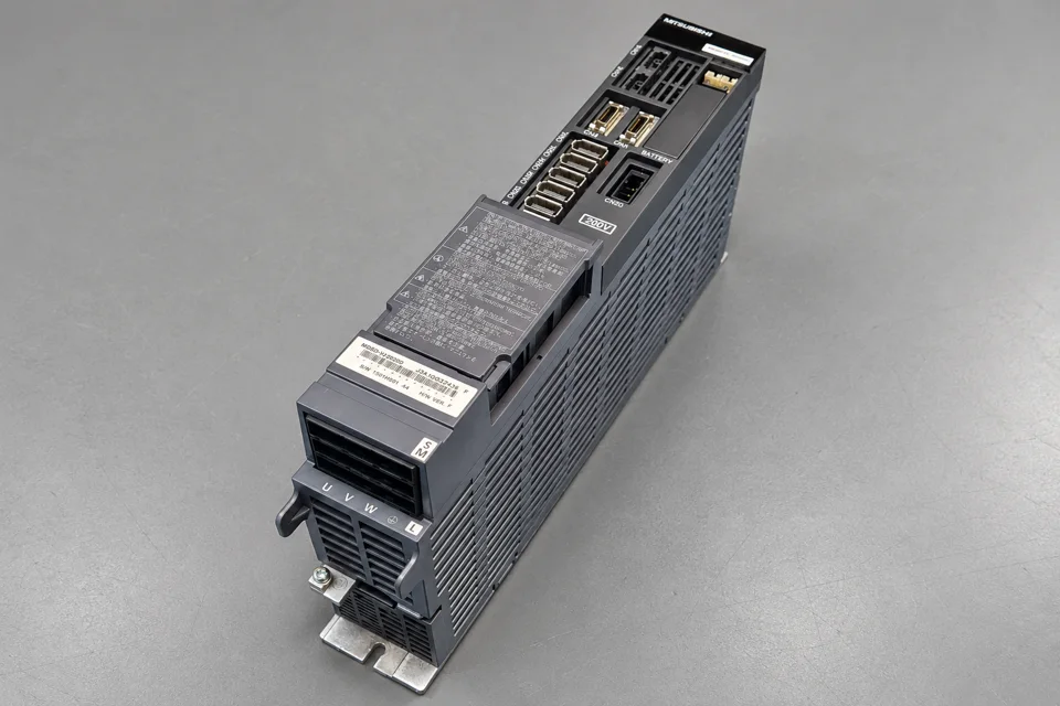 Overhauled replacement unit
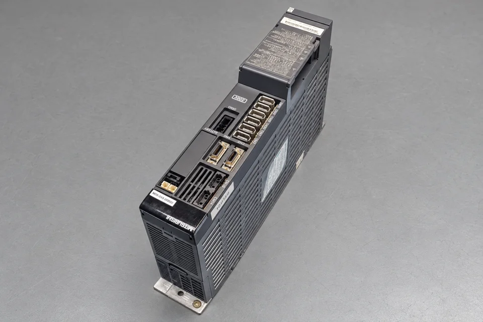 Replacement unit, additional view
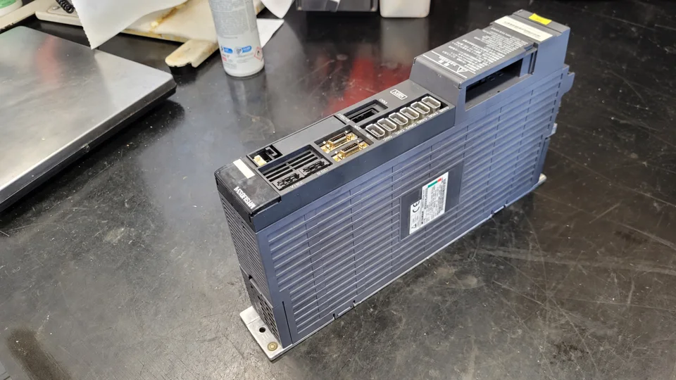 Original failed unit
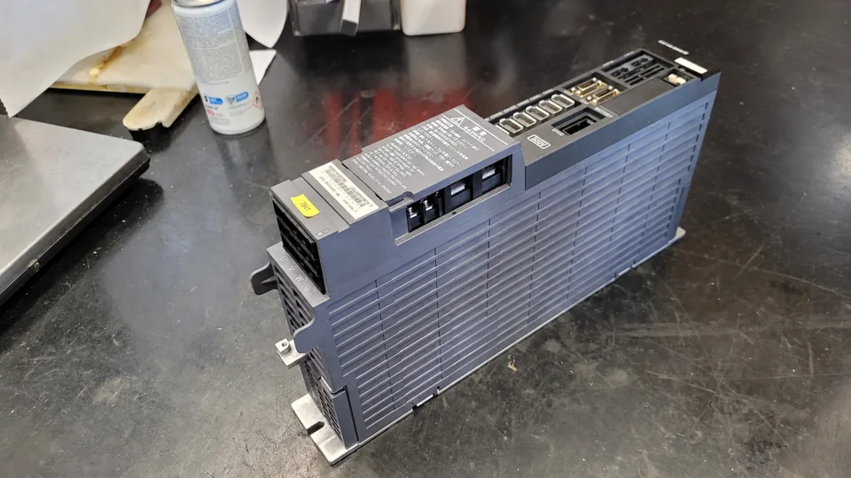 Original unit before inspection
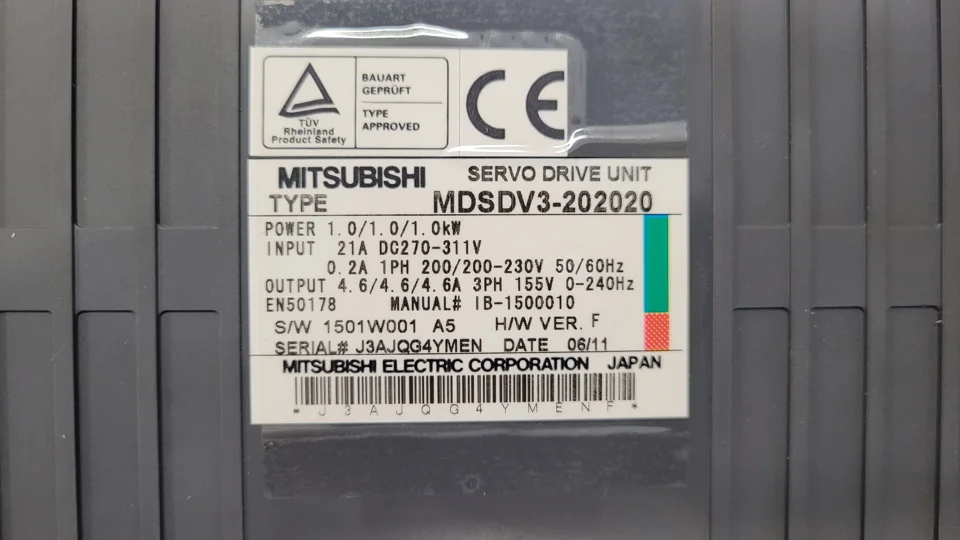 Nameplate of the original unit
Request repair or replacement support
Send the complete model designation, photographs of every unit label, machine model and control version, together with alarm numbers, timing and affected axes. Available parameter backups and information about previous changes assist the compatibility check. This helps establish whether repairing the existing unit or preparing a replacement is the appropriate approach.
Mitsubishi MDS-D-V3-202020 in our shop · More Mitsubishi units at industrypart
Technical sources: photographed original nameplate; documented information for this Citizen case; Mitsubishi Electric MDS-D/DH Series Instruction Manual, IB-1500025H, alarm reference 6-2-1. Series documentation supplements this case report and does not replace machine-specific commissioning instructions.