22.10.2026 by Viktor Siebert
Mitsubishi MDS-CH-V2-4520: Motor vibration – power stage repair
The X-axis of a Mazak Integrex intermittently vibrated and hummed strongly at standstill. According to the customer, the Mitsubishi MDS-CH-V2-4520 displayed no drive fault; the machine reported overload after several seconds of vibration. At industrypart, abnormal motor behaviour was reproduced at different speeds. Repair addressed the power output stage and its transistor drive circuitry, accompanied by a preventive overhaul.
Technical specifications and identification
| Item | Specification |
|---|
| Modell / Model | Mitsubishi MDS-CH-V2-4520 |
| Bauart / Type | 2-Achs-Servoantrieb / 2-axis servo drive |
| Leistungszuordnung / Rated output | 4,5 + 2,0 kW / 4.5 + 2.0 kW |
| Leistungseingang / Main input | 513–648 V DC; 14,7 A / 14.7 A |
| Ausgang / Output | max. 456 V AC; 11,0 / 5,0 A / 11.0 / 5.0 A |
| Steuerversorgung / Control supply | 380–440 V AC (50 Hz); 380–480 V AC (60 Hz); max. 0,1 A / 0.1 A |
| Regelung / Control | Sinus-PWM / Sine-wave PWM |
| Kühlung / Cooling | Zwangsluft / Forced air |
| Schutzart / Protection | IP00 |
| Betriebsumgebung / Operating environment | 0–55 °C; ≤90 % RH, ohne Kondensation / non-condensing |
These values are from Mitsubishi manual BNP-C3016(ENG)F, section 10-1-2, page 10-2. Its note identifies output voltage as a maximum and output current as continuous motor rated current. They are not measurements from this repair. This is a 400 V-class model; specifications for MDS-C1 or the later MDS-CH-N series must not be transferred without verification.
Machine application and interchangeability
The customer identifies a Mazak Integrex as the source machine. This documents the application of this particular drive, rather than establishing compatibility with every Integrex version. A V2 drive contains two axis channels. Assignment of machine axes to those channels depends on actual wiring and configuration. No second affected axis was reported.
Replacement and recommissioning require the complete model designation, hardware and software versions, motor, feedback and machine parameters to be considered together. Matching power alone does not establish interchangeability. The existing machine configuration must not be replaced with an apparently similar standard parameter set. The customer-machine motor model and individual circuit-board part numbers are not documented for this report.
Energy flow, control and feedback
The power stage converts DC-bus energy into controlled motor currents. Power transistors switch according to their driver circuitry, allowing the motor to develop torque. Feedback lets the control system compare actual movement with the command. An enabled axis at standstill may still require holding torque: zero speed does not mean that the power stage is inactive.
Uneven current generation can produce torque fluctuations. This provides a technically plausible connection between an output-stage or driver fault and vibration or humming. Without published current traces, however, it does not establish a particular switching pattern or exact electrical mechanism. Similar vibration symptoms can have different causes.
Functional sections and documented work
| Section | Function and case relevance |
|---|
| Power output stage | Motor power conversion; repaired and power transistors replaced |
| Power-transistor driver circuitry | Switching signals and associated driver function; repaired |
| Control and feedback processing | Command and feedback evaluation; no specific board identifier documented |
| Heatsink and airflow paths | Heat removal; visible in the photographs, but no separate fan replacement reported for this case |
This overview describes functional sections. It does not state that complete boards were exchanged. Confirmed work comprises transistor replacement, repair of their driver circuitry and preventive overhaul.
Customer report and workshop findings
| Level | Documented observation |
|---|
| Customer machine | Intermittently strong X-axis vibration/humming at standstill |
| Indication | No drive fault reported; machine overload after several seconds |
| Previous customer work | Encoder replaced and considered excluded as the cause by the customer |
| industrypart inspection | Motor vibrates at different speeds |
| Repair | Power stage and driver circuitry repaired; preventive overhaul |
The workshop inspection confirmed abnormal behaviour and extended beyond the originally reported standstill condition. Keeping these observations separate helps avoid attributing the problem prematurely to one holding position or exclusively to standstill regulation.
Why an encoder replacement does not complete the diagnosis
The previous encoder replacement is an important part of the history. It does not replace evaluation of the entire feedback chain. Connectors, cables, shielding, supply, input processing and system settings can be affected independently of the detector itself. This report does not claim that all these items were separately measured in this case.
For a comparable symptom, professional diagnosis also considers the motor and power cable, mechanical resistance, coupling, brake, supply and parameters. Comparing cold and warm conditions, standstill and motion, different speeds and directions can help establish a pattern. These are general diagnostic considerations, not an expanded record of work actually performed. On this unit, diagnosis led to repair of the power stage.
No drive alarm does not establish fault-free operation
An absent fault indication is not a comprehensive health certificate. Monitoring functions respond to particular quantities, conditions and time histories. Abnormal motor behaviour can occur before a particular protection threshold is reached. Conversely, an overload alarm identifies an overload condition rather than automatically identifying a failed component.
The actual Mazak overload alarm number was not supplied, so it is not assigned to drive alarm 50 or 51 here. The “A8” sticker visible in a photograph is not a documented alarm indication either. For subsequent investigation, the complete message, number, affected axis and timing are more useful than a shortened description.
Selected relevant MDS-CH alarm groups
This concise reference is based on BNP-C3016(ENG)F, chapter 8, pages 8-5 to 8-12. It is not a list of drive alarms observed in this repair. Applicability also depends on the feedback system and machine configuration.
| Code | Meaning, paraphrased |
|---|
| 20 | Motor feedback signal missing |
| 21 | Machine feedback signal missing |
| 2F | Motor detector communication fault |
| 31 | Overspeed |
| 32 | Power-module overcurrent |
| 33 | Overvoltage |
| 34 | CNC data/CRC fault |
| 36 | CNC communication loss |
| 3A | Excessive motor current |
| 3B | Power-module overheating |
| 42 | Feedback fault 1 |
| 43 | Feedback fault 2 |
| 46 | Motor overheating |
| 50 / 51 | Overload 1 / 2 |
| 52 / 53 | Position deviation 1 / 2 |
The group guides investigation: feedback messages point toward the signal chain, communication messages toward data exchange, and current or temperature messages toward electrical or thermal stress. Overload and position deviation may arise from a disturbed drive chain or unusual mechanical demand. A code alone does not justify blanket component replacement. Settings and protection limits should not be changed experimentally to conceal an unidentified fault.
Repair and test footage
We repaired the power output stage, replaced its power transistors and restored their driver circuitry. Considering both the semiconductors and their drivers matters: replacing a transistor does not automatically correct faulty drive signals. The unit also received a preventive overhaul. This report does not include a detailed list of additional replaced components.
The video includes the supplied original test-bench footage; the photographs document the unit before and after repair. The recording provides a view of the inspection rather than replacing a measurement report. No additional claims are made regarding load, testing duration beyond the recording, or subsequent operation in the customer machine.
Prevention and information for a repair enquiry
Routine maintenance should include attention to contaminated airflow paths and heatsinks, together with early documentation of changes in sound, temperature or axis behaviour. Cable stress, secure connectors and changes following maintenance can also provide useful clues. Preventive overhaul can reduce ageing-related weaknesses, but does not guarantee a specified remaining service life.
A useful enquiry includes the complete drive designation, a legible nameplate, machine and axis identification, and a short sequence describing the fault. Previously replaced parts should be stated explicitly. Work on the power stage and DC bus belongs with qualified personnel, with stored electrical energy addressed before intervention.
Source
Mitsubishi Electric: MDS-CH Series Specifications Manual, BNP-C3016(ENG)F — 1-3, 8-5–8-12, 10-2. Case facts and photographs: supplied workshop documentation.
Repair video and photographs
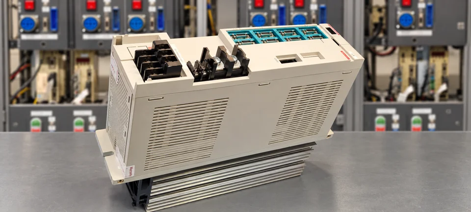 After repair – side view
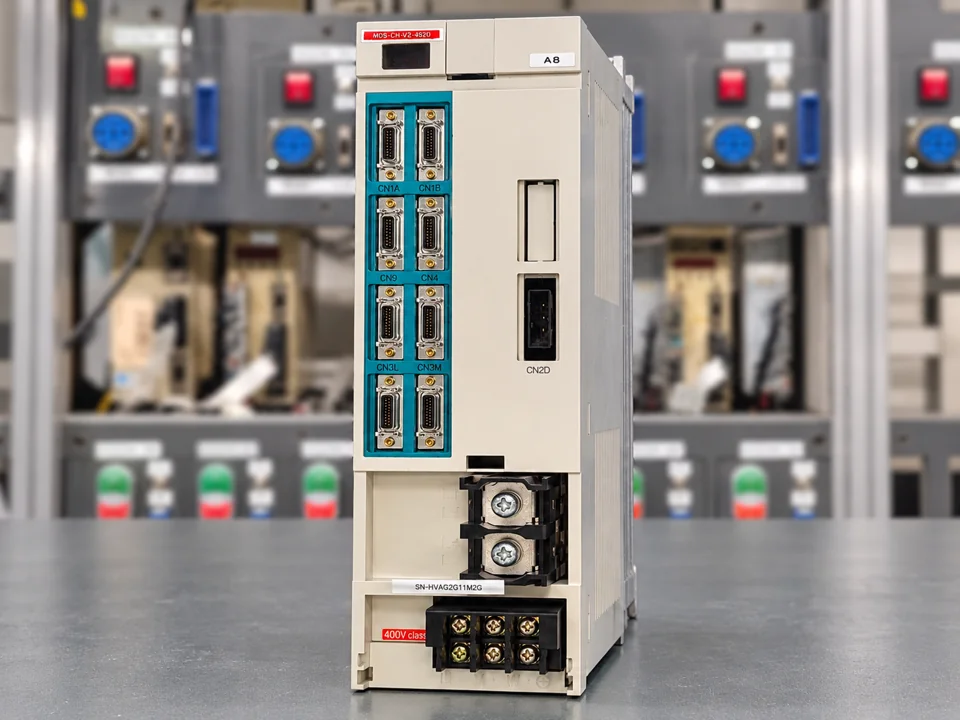 After repair – front view
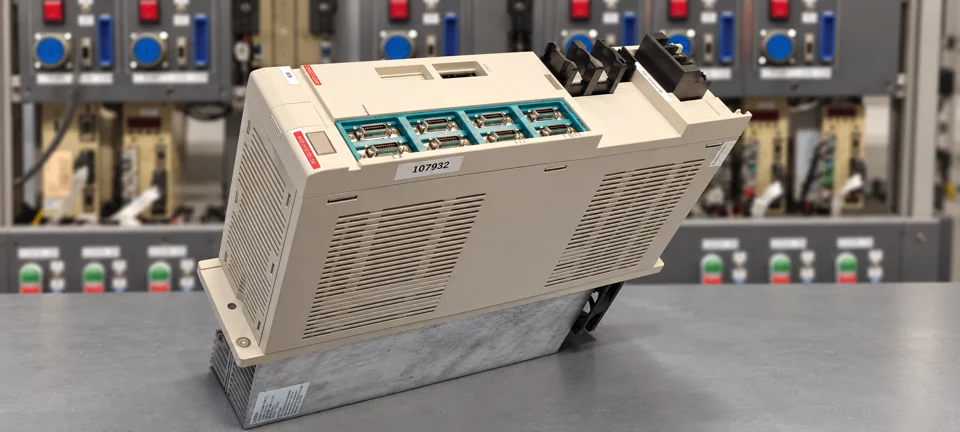 After repair – rear view
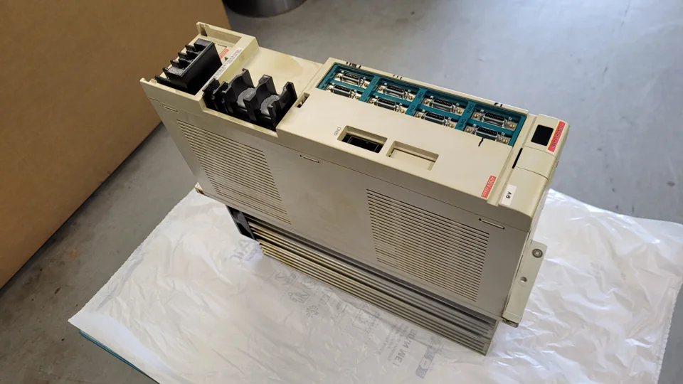 Before repair – side view
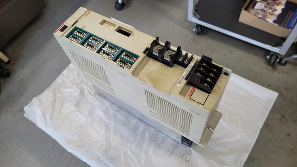 Before repair – terminals
Request a repair
Does your Mitsubishi drive exhibit abnormal motor behaviour? Visit our Mitsubishi page for repair services and products.