26.07.2026 by Viktor Siebert
Mitsubishi MDS-CH-V2-3535 Servo Drive Unit with Alarm 32 Overcurrent Fault Successfully Eliminated After Thermal Damage
Unexpected production downtime often results in high costs, delayed deliveries and significant interruptions in manufacturing. This was exactly the situation one of our industrial customers faced when their CNC machine repeatedly stopped during operation due to Alarm 32. The affected unit was a Mitsubishi MDS-CH-V2-3535 AC Servo Drive Unit responsible for controlling multiple servo axes within the machine.
Initially, the fault occurred only occasionally. After a short operating period, Alarm 32 appeared and the machine had to be restarted. Over time, the intervals between failures became shorter until reliable production was no longer possible.
During the initial technical discussion with the customer, we suspected that, in addition to an electrical fault, thermal influences might also be contributing to the problem. The drive unit was therefore shipped to our repair facility for a complete inspection.
Initial Diagnosis
After the drive arrived at our workshop, the first step was a comprehensive visual inspection.
Even before carrying out electrical measurements, one important defect became immediately apparent.
The internal cooling fan was completely seized and could no longer rotate. Significant dust and contamination had accumulated over time, severely restricting the airflow through the cooling system. As a result, the power electronics were no longer able to dissipate the generated heat efficiently.
Following the visual inspection, the unit underwent a complete electrical evaluation.
Among other things, the following assemblies were examined:
- Power supply sections
- DC bus
- Power stage
- IGBT power module
- Gate driver circuits
- Current measurement circuits
- Insulation values
- Connectors
- Heat sinks
- Cooling fan supply
During these tests, the customer’s reported Alarm 32 could be reproduced.
According to the Mitsubishi documentation, Alarm 32 indicates “Power Module Error (Overcurrent).” The alarm is generated whenever the power module detects an overcurrent condition. The manufacturer’s service manual lists possible causes including short circuits, failures within the power module itself, defective motors or damaged motor power cables.
In this particular repair case, however, our inspection also revealed a clear connection between the alarm and the failed cooling system.
Root Cause Analysis
After completing all electrical and mechanical inspections, the following damage pattern became evident:
- Completely seized cooling fan
- Severely reduced cooling performance
- Long-term thermal stress on electronic components
- Elevated operating temperatures inside the power stage
- Power module overcurrent shutdown resulting in Alarm 32
- Early ageing of heat-sensitive electronic components
Our technical assessment was therefore as follows:
The seized cooling fan caused insufficient heat dissipation over an extended period. As a consequence, the temperature of the power electronics increased significantly. Under higher machine loads, the power module operated outside its optimal temperature range until its internal protection system finally detected an abnormal operating condition and triggered Alarm 32.
This diagnosis perfectly matched the physical condition of the drive. While Mitsubishi generally classifies Alarm 32 as an overcurrent fault of the power module, the failed cooling system was identified in our workshop as the most probable underlying cause that initiated the failure sequence.
Repair Process
After customer approval, the Mitsubishi Servo Drive underwent a complete industrial repair.
The following work was carried out:
- Complete disassembly
- Professional industrial cleaning
- Replacement of the seized cooling fan
- Inspection of all power semiconductors
- Verification of all gate driver circuits
- DC bus inspection
- Inspection of the power supply sections
- Examination of all connectors
- Re-soldering of thermally stressed solder joints
- Preventive inspection of heat-sensitive components
- Cleaning of all cooling surfaces
- Renewal of thermal interfaces where required
- Final electrical safety inspection
Special attention was paid to every assembly that may have suffered from long-term thermal stress to ensure maximum long-term reliability after the repair.
Final Testing and Return to the Customer
After completing the repair, the Mitsubishi MDS-CH-V2-3535 Servo Drive Unit underwent extensive testing on our dedicated industrial test bench.
Among other things, the following functions were verified:
- Power-up behaviour
- DC bus voltage
- Current consumption
- Servo axis control
- Power output performance
- Temperature development
- Long-term load test
- Protection functions
- Communication
- Cooling fan operation
The newly installed cooling fan operated flawlessly throughout the entire endurance test. Even under increased load, the temperature of the power electronics remained completely stable.
Alarm 32 did not occur again at any point during the complete testing procedure.
Only after successfully passing all functional and load tests was the drive released for shipment back to the customer.
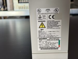
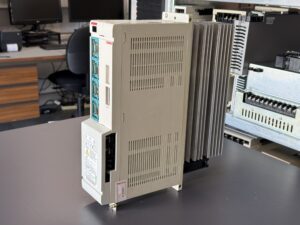
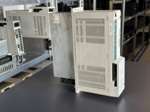
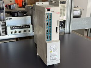
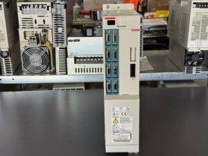
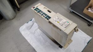
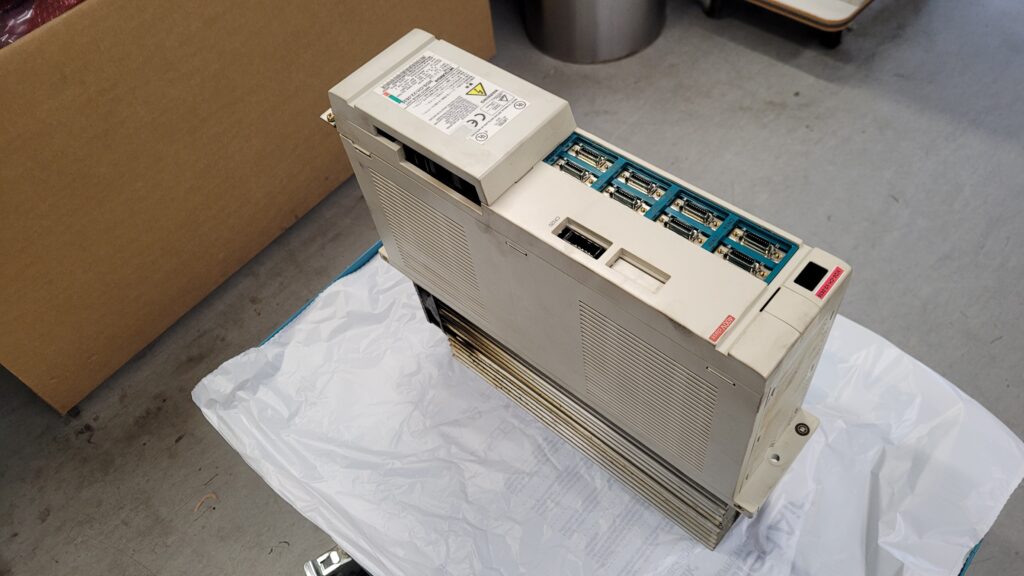
To mentioned Mitsubishi Drive: Mitsubishi MDS-CH-V2-3535 Servo Drive
More details about our Mitsubishi repair services can be found here:
Mitsubishi drive Repair by Industrypart
📞 Feel free to contact us with any questions about your Mitsubishi drive technology.
Our expert team is happy to help!
Technical Specifications
| Property | Value |
|---|
| Manufacturer | Mitsubishi Electric |
| Model | MDS-CH-V2-3535 |
| Device Type | AC Servo Drive Unit |
| Series | MDS-CH-V2 |
| Year of Manufacture | May 2010 (Nameplate) |
| Power Supply | Part of the Mitsubishi MDS multi-axis drive system |
| Cooling | Forced-air cooling via integrated cooling fan |
| Power Stage | 35 / 35 Servo Axes |
| Application | CNC Machine Tools |
| Diagnostics | LED display with alarm numbers |
| Protective Functions | Overcurrent, overvoltage, overload, cooling fan monitoring, temperature monitoring, regeneration protection, communication monitoring, detector monitoring |
Operating Conditions
| Parameter | Value |
|---|
| Installation Location | Electrical cabinet |
| Environment | Low-dust industrial environment |
| Adequate Ventilation | Required |
| Regular Cleaning | Recommended |
| Heat Sink | Must be kept free from dust |
| Cooling Fan | Should be inspected regularly |
| Humidity | Condensation must be avoided |
| Mechanical Stress | Low vibration |
Cooperation with Other Devices
The Mitsubishi MDS-CH-V2-3535 Servo Drive Unit is part of the modular Mitsubishi MDS drive system and operates together with various components within a CNC control system.
Compatible components include:
- Mitsubishi MDS-C1 Power Supply Unit
- Mitsubishi MDS-D Power Supply Unit
- Mitsubishi AC Servo Motors
- Mitsubishi Spindle Motors
- Mitsubishi CNC Controllers
- MELDAS CNC Systems
- Serial Encoders
- Absolute Encoders
- Incremental Encoders
Communication between the CNC controller, power modules and position encoders is continuously monitored. Communication errors, detector errors or parameter errors are immediately detected and displayed as alarms.
Functional Description
The Mitsubishi MDS-CH-V2-3535 Servo Drive Unit is responsible for the highly dynamic control of connected servo axes in modern CNC machine tools.
Based on the command values received from the CNC controller, the drive continuously calculates current, torque and speed commands for the connected servo motors. At the same time, the encoder feedback signals are permanently evaluated and compared with the commanded values.
During operation, the unit continuously monitors numerous protective functions, including:
- DC bus voltage
- Motor current
- Power modules
- Power electronics temperature
- Cooling fan operation
- Communication between controller and drive
- Encoder communication
- Regenerative energy
- Overload conditions
- Power supply voltage
If any operating limits are exceeded, the system automatically protects itself by disabling the power output stages or by performing a controlled deceleration of the axes. This protects not only the drive itself but also the motors and the machine from consequential damage.
Alarm and Fault Codes
| Alarm | Fault Name | Description | Reset | Corrective Action |
|---|
| 10 | Insufficient Voltage | DC bus voltage too low | PR | Check the power supply |
| 17 | A/D Converter Error | Current feedback fault | PR | Inspect the drive |
| 23 | Excessive Speed Error | Excessive speed deviation detected | NR | Check motor and parameters |
| 24 | Grounding | Motor power cable grounded | PR | Inspect motor and power cables |
| 30 | Over Regeneration | Excessive regenerative energy | PR | Check braking resistor |
| 31 | Overspeed | Motor speed exceeded the allowable limit | PR | Check encoder and control loop |
| 32 | Power Module Error (Overcurrent) | Overcurrent detected in the power module | PR | Inspect the power stage, motor, cables and power module |
| 33 | Overvoltage | DC bus voltage too high | PR | Check power supply |
| 38 | Motor Overload | Electronic motor overload protection activated | NR | Reduce the mechanical load |
| 45 | Fan Stop | Cooling fan failure detected | PR | Inspect or replace the cooling fan |
| 46 | Motor Overheat | Motor or thermal protection overheated | NR | Check cooling system and motor |
| 50 | Overload 1 | Overload detected | NR | Reduce the machine load |
| 51 | Overload 2 | Continuous high motor current detected | NR | Inspect mechanics and load |
| 61 | Power Module Overcurrent | Overcurrent detected in the power supply module | PR | Inspect the power module |
| 71 | Instantaneous Power Interruption | Temporary power failure detected | NR | Check the power supply |
| 73 | Over Regeneration | Regenerative energy exceeded the allowable level | NR | Inspect the braking resistor |
| 75 | Overvoltage | DC bus overvoltage | NR | Check power supply and regenerative circuit |