11.01.2026 by Viktor Siebert
Repair of a Mitsubishi MDS-C1-V1-35 Servo Drive Unit with Alarm 32 and Motor Noise
Initial situation and fault description.
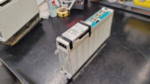
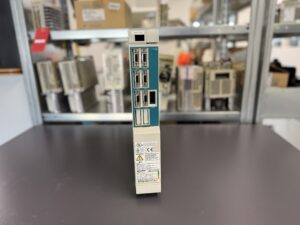
The Mitsubishi Servo Drive Unit MDS-C1-V1-35 was sent in by the customer due to abnormal motor noise during operation. In addition, the CNC control reported Alarm 32, which indicates an overcurrent condition in the power module.
According to the customer, the motor noise occurred shortly after axis activation and increased under load. The axis had previously operated without noticeable issues, and the fault appeared suddenly during normal production.
Initial assessment and typical causes
Alarm 32 on Mitsubishi MDS-C1 servo drives is a serious indication related to the power stage. In practice, this alarm is frequently associated with:
- axis overload conditions
- insulation issues at the motor
- internal defects within the power stage
- age-related degradation of electronic components
Because mechanical motor noise was reported at the same time, both the servo drive and the interaction between drive and motor had to be considered during diagnosis.
Incoming inspection and visual check
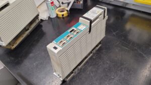
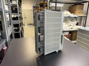
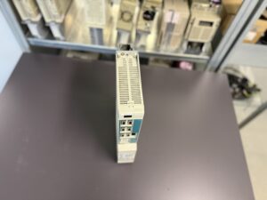
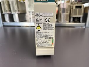
After receipt of the unit, a detailed visual inspection was performed.
No burn marks, visible damage, or contamination were detected. Connectors, power terminals, and the housing were in proper condition.
The unit was then prepared for further diagnostic testing.
Testing on the servo test system
The MDS-C1-V1-35 was operated on our CNC-like servo test system in order to reproduce the fault under controlled conditions.
During the first test runs, irregularities in the current behavior of the axis became apparent. Under load, unstable control states occurred, which were clearly audible as motor noise. Shortly thereafter, Alarm 32 could be reproduced reliably.
This confirmed that the root cause was not limited to the motor or cabling but was located within the servo drive itself.
Diagnosis and root cause
Detailed analysis revealed abnormalities in the power section of the servo drive.
Due to aging and long-term thermal stress, internal characteristics of the power electronics had drifted over time. This resulted in distorted current measurement signals and unstable motor control.
Such conditions can lead to increased current peaks, which trigger the overcurrent protection. At the same time, the motor may produce audible noise even though no mechanical defect is present.
Repair work performed
As part of the repair, the MDS-C1-V1-35 was completely disassembled and professionally cleaned.
The control and power assemblies were tested individually, critical areas were reworked, and the power stage was refurbished.
Special attention was paid to restoring stable current measurement and proper power stage control. The objective was to reestablish the original control stability of the servo drive.
Firmware, software, and customer-specific parameter settings remained unchanged throughout the entire repair process.
Final testing and result
After completion of the repair, the unit was retested on the servo test system.
The motor now operated smoothly and quietly, both at idle and under load. The previously reported motor noise was completely eliminated.
Extended test cycles confirmed stable control behavior, and Alarm 32 no longer occurred.
Only after successful long-term testing was the servo drive released for return shipment to the customer.
Conclusion
This repair case demonstrates that motor noise combined with Alarm 32 does not necessarily indicate a defective motor. In many cases, the root cause is located within the servo drive itself, particularly in the power electronics.
A focused electronic diagnosis and realistic load testing are essential to avoid unnecessary motor replacement and to identify the true source of the problem.
To mentioned Mitsubishi Drive: Mitsubishi Power Supply Unit MDS-C1-CV-75
More details about our Mitsubishi repair services can be found here:
Mitsubishi drive Repair by Industrypart
📞 Feel free to contact us with any questions about your Mitsubishi drive technology.
Our expert team is happy to help!
Application Information
The Mitsubishi MDS-C1-V1-35 Servo Drive Unit is typically used in CNC machine tools such as machining centers, lathes, and special-purpose machines.
It is designed for feed axes requiring precise speed and position control and is commonly paired with Mitsubishi AC servo motors from the HF and HA series.
Typical environments include production systems with continuous operation, frequent acceleration and deceleration cycles, and varying mechanical loads. In such applications, long-term thermal stress can contribute to aging effects within the drive electronics.
Alarm Messages and Troubleshooting
Alarm Table Mitsubishi MDS-C1-V1-35
| Alarm code | Description | Meaning | Possible cause | Recommended action |
|---|
| 32 | Power Module Overcurrent | Overcurrent detected in the power module | Power stage instability, aged electronics, current measurement deviation | Inspect and repair servo drive power section |
| 3A | Overcurrent | Excessive motor current detected | Unstable control loop, electrical faults | Check drive electronics and motor wiring |
| 50 | Overload 1 | Overload level exceeded | Increased current demand due to instability | Inspect drive and operating conditions |
| 51 | Overload 2 | Continuous high current | Long-term control instability | Evaluate servo drive electronics |
| 23 | Excessive Speed Error | Speed deviation too large | Control loop instability | Test servo drive under load |
| 28 | Excessive Position Error | Position deviation exceeded | Unstable regulation, signal distortion | Inspect control electronics |
Technical Information Mitsubishi MDS-C1-V1-35
Technical Specifications
| Parameter | Value |
|---|
| Manufacturer | Mitsubishi Electric |
| Device type | Servo Drive Unit |
| Model | MDS-C1-V1-35 |
| Rated power | 3.5 kW |
| DC bus voltage | DC 270–311 V |
| DC input current | 17 A |
| Control input voltage | Single-phase 200–230 V AC |
| Control input current | 0.2 A |
| Mains frequency | 50 / 60 Hz |
| Output voltage | Three-phase 155–240 V AC |
| Output current | 16 A |
| Standards | EN50178 |
| Documentation | Manual BNP-C3000 |
| Software version | BND582W000A1 |
| Hardware version | C |
| Date of manufacture | 2000-11 |
| Country of origin | Japan |
Main Components
| Assembly | Board designation | Quantity |
|---|
| Control board | RK112A-21 or BN634A980G51 B | 1 |
| Power board | RL122B-V1 BN638A153G51 A | 1 |
| Power section | Power unit | 1 |